Four-terminal Alloy Shunt Resistors (FLH)
Alloy Shunts (FLH) Introduction
Four-terminal Alloy Shunt Resistors (FLH) tackle current sensing applications with TCR 20ppm.
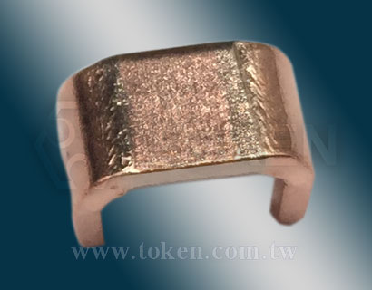
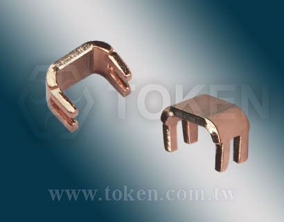
Token FLH open four-pin alloy shunt series, also known as four-lead sampling shunt, current sensing resistor, or four-pin sampling resistor.
Kelvin four-terminal resistors are used to ensure that the current acts on two opposite terminals and to measure the detection voltage of the other two terminals, thereby reducing the influence of resistance and temperature coefficient between terminals and obtaining more accurate current measurements.
Four-lead alloy shunt FLH adopts U-shaped design and high-pulse special alloy element structure, which can improve the power of the resistor and expand the operating temperature range. It has the characteristics of low resistance, low inductance and high reliability. The temperature coefficient is lower than that of 20 ppm/C, which provides excellent performance and is suitable for various applications.
Token FLH devices always preferred in current sense applications, standard rated power 3W is available packages, resistance values down to 0.0003Ω, with tolerances as tight as ±1%, ±2%, and ±5% with low-inductance 10 nH. TCR is as low as ±20ppm/°C and ±50ppm/°C with high-impulse proprietary metal element that gives the device its extended power and temperature ratings.
With modern technology and production methods, we continuously upgrade production equipment, provide complete low resistance current detection resistor products, and all aspects of current sensing shunt product information and application information. The products meet RoHS requirements.
FLH series as current divider and current detection resistor products can be customized according to customers'needs. For special resistance value and latest product information, contact us with your specific needs.
Downloads Complete Specification PDF: Four-terminal Alloy Shunt Resistors (FLH).
- Resistance values down to 0.0003Ω.
- TCR down to ±20ppm/°C and ±50ppm/°C.
- Low inductance. RoHS compliant and Lead-free.
- Tolerance ±1%, ±2% and ±5%. Rated Power 3 Watts.
- Current Sensing, Drive technology.
- Automotive electronics, Power Electronic.
- Communication System, Home Appliance.
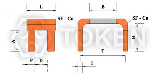
Alloy Shunt Resistors (FLH) Dimensions (Unit:mm)
Alloy Shunt Resistors (FLH) - Dimensions |
||||||||
| Type | B (mm) | W (mm) | L (mm) | A (mm) | P (mm) | H (mm) | D (mm) | I (mm) |
| FLH-M-0m30 | 5.0±0.3 | 8.3±0.3 | 5.3±0.3 | 3.8±0.5 | 1.3±0.3 | 5.0±1.0 | 1.8±0.3 | 1.43±0.3 |
| FLH-M-0m50 | 5.0±0.3 | 8.3±0.3 | 5.3±0.3 | 3.8±0.5 | 1.3±0.3 | 5.0±1.0 | 1.8±0.3 | 0.86±0.3 |
| FLH-M-R001 | 5.0±0.3 | 8.3±0.3 | 5.3±0.3 | 3.8±0.5 | 1.3±0.3 | 5.0±1.0 | 1.8±0.3 | 0.44±0.3 |
| FLH-M-R002 | 5.0±0.3 | 8.3±0.3 | 5.3±0.3 | 3.8±0.5 | 1.3±0.3 | 5.0±1.0 | 1.8±0.3 | 0.63±0.3 |
| FLH-M-R003 | 5.0±0.3 | 8.3±0.3 | 5.3±0.3 | 3.8±0.5 | 1.3±0.3 | 5.0±1.0 | 1.8±0.3 | 0.43±0.3 |
Alloy Shunt Resistors (FLH) Surface Temperature Curve
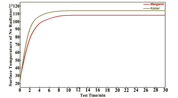
FLH - Surface Temperature Curve |
Alloy Shunt Resistors (FLH) TCR Derating Curve

FLH - TCR Derating Curve |
Alloy Shunt Resistors (FLH) Environmental Characteristics
| Items | Requirement | Test Methods |
| Temperature Cycling | ±0.5% | JESD22 1000 Cycles(-55°C to +125°C). Measurement at 24±2 hours after test conclusion. |
| High Temperature Exposure | ±0.5% | MIL-STD-202 1000hrs. @T=125°C. Unpowered. Measurement at 24±2 hours after test conclusion. |
| Moisture Resistor | ±0.5% | MIL-STD-202 t = 24 hrs/cycle. Steps 7a & 7b not required. Unpowered. Measurement at 24±2 hours after test conclusion. |
| Biased Humidity | ±0.5% | MIL-STD-202 1000hrs 85°C/85% RH. Note: Specified conditions: 10% of operating power. Measurement at 24±2 hours after test conclusion. |
| Operational Life | ±0.5% | MIL-STD-202 Condition D Steady State TA=125°C at rated power. Measurement at 24±2 hours after test conclusion. |
| Solderability | 95% Coverage Minimum. | J-STD-002C 245±5°C, 5s+0.5s/-0. |
| Vibration | ±0.5% | MIL-STD-202 5g's for 20 min, 12 cycles each of 3 orientations. Note: Use 8"X5" PCB. 031" thick 7" secure points on one long side and secure points at corners of opposite sides which parts mounted within 2 from any secure point. Test from 10-2000 Hz. Measurement at 24±2 hours after test conclusion. |
| Resistance to Soldering Heat | ±0.5% | MIL-STD-202 260±5°C, 10s±1s. Measurement at 24±2 hours after test conclusion. |
| Short Time Overload | ±0.5% | MIL-STD-202 55×Rated power for 5s. Measurement at 24±2 hours after test conclusion. |
| Thermal Shock | ±1% | MIL-STD-202 -55°C/+125°C, 300 Cycles. Maximum transfer time 20s, Dwell time 15min. |
Alloy Shunt Resistors (FLH) Derating Curve
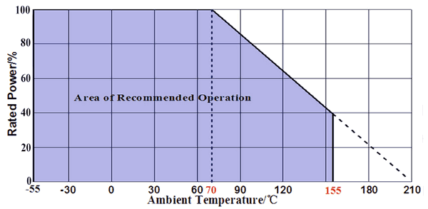
Rated power VS Ambient temperature (Power Derating Cruve) |
Alloy Shunt Resistors (FLH) Internal Package
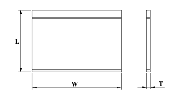
FLH - Internal Package |
|||
| Type | L/mm | W/mm | T/mm |
| P1 | 130 | 130 | 0.2 |
| P2 | 160 | 160 | 0.2 |
| P3 | 210 | 150 | 0.1 |
Alloy Shunt Resistors (FLH) External Package
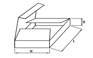 FLH - External Package |
|||
| Type | L/mm | W/mm | H/mm |
| B1 | 170 | 120 | 50 |
| B2 | 240 | 180 | 115 |
| B3 | 230 | 170 | 200 |
| B4 | 250 | 250 | 250 |
| B5 | 300 | 300 | 300 |
Four-Lead Alloy Shunts (FLH) Order Code
| FLH | M | 0m30 | F | ||||||||||||||||||||||||
 |
|
|
|
||||||||||||||||||||||||
|
|
|
|
||||||||||||||||||||||||