Chip Alloy Current Shunt Resistors (FLM)
Alloy Shunt Chips (FLM) Introduction
SMD alloy shunt resistance FLM is a key current sensing technology for future vehicle construction.
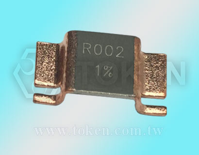
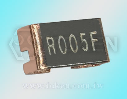
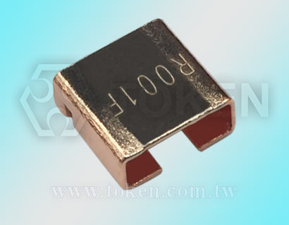
Token Electronics equipped with (FLM) alloy shunt on its current sensing surface mount devices. It adopts the design of folding terminals outward and inward. Nickel-copper or manganese-copper alloy stamping is used to maintain the superior electrical characteristics of the surface mounting structure. It has the characteristics of pulse resistance and high precision.
Unlike other manufacturers of metal alloy current detection resistors, Token metal alloy power chips (FLM) have a number of advantages. Power can reach 4W, 5W, and 7W. The temperature coefficient TCR (20 - 50) ppm, tolerance accuracy 1%, 2%, and 5%, is used to improve the measurement accuracy. The resistance value is as low as 0.0002Ω, which is the first choice for high-end current sensing and sampling applications.
The (FLM) device is applicable to all types of voltage dividers, current detection and pulse applications in power management, such as sensors and transducers; VRM for notebook computers, DC/DC converters for servers, management and safety of lithium ion batteries; industrial instrumentation; and high current applications in the automotive market, such as audio, transmission, anti-lock braking, and engines.
Token Electronics adopts modern technology and production methods, constantly upgrades production equipment, provides complete low resistance current detection components, and all aspects of current sensing shunt product and application information.
The (FLM) device is available in bulk packaging and is RoHS compliant and lead free. For non-standard technical requirements and special applications, contact us with your specific needs.
Downloads Complete Specification PDF Alloy Current Shunt Chips (FLM).
- Rated Power 4W ~ 7W. Tolerance ±1%,±2% and ±5%.
- Inductance less than 10 nH, Lead-free and RoHS compliant.
- Resistance values down to 0.0002Ω. TCR down to ±20ppm/°C and ±50ppm/°C.
- Current sensor for power hybrid applications.
- Power modules, High current applications for the automotive market.
- Communication system, Frequency converters, Automatic control power supply.
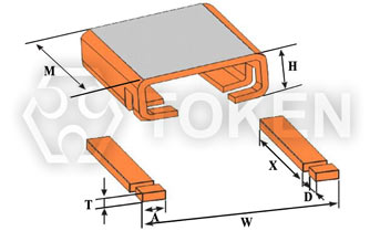
Metal Alloy Power Shunts (FLM) Dimensions (Unit:mm)
Alloy Shunt Resistors FLM - Inward Fold (n)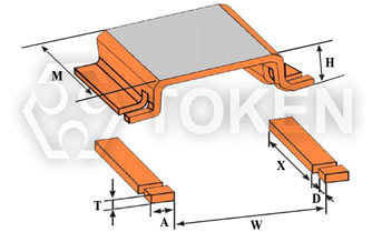
Alloy Shunt Resistors FLM - Outward Fold (y) |
||||||||
| Type | Power (W) | M (mm) | W (mm) | H (mm) | X (mm) | D (mm) | A (mm) | T (mm) |
| FLM-M-0m20 | 5 | 6.6±0.3 | 6.9±0.3 | 3.0±0.5 | 4.8±0.3 | 0.90±0.3 | 2.5±0.3 | 0.7±0.3 |
| FLM-M-0m30 | 5 | 6.6±0.3 | 6.9±0.3 | 3.0±0.5 | 4.8±0.3 | 0.90±0.3 | 2.5±0.3 | 1.12±0.3 |
| FLM-M-0m50 | 5 | 6.6±0.3 | 6.9±0.3 | 3.0±0.3 | 4.8±0.3 | 0.90±0.3 | 2.5±0.3 | 0.66±0.3 |
| FLM-M-R001 | 5 | 6.6±0.3 | 6.9±0.3 | 3.0±0.3 | 4.8±0.3 | 0.90±0.3 | 2.5±0.3 | 0.33±0.3 |
| FLM-K-R002 | 5 | 6.6±0.3 | 6.9±0.3 | 3.0±0.3 | 4.8±0.3 | 0.90±0.3 | 2.5±0.3 | 0.50±0.3 |
| FLM-K-R003 | 4 | 6.6±0.3 | 6.9±0.3 | 3.0±0.3 | 4.8±0.3 | 0.90±0.3 | 2.5±0.3 | 0.34±0.3 |
| FLM-K-R005 | 4 | 3.9±0.3 | 6.9±0.3 | 3.0±0.3 | 2.0±0.3 | 0.34±0.3 | 2.5±0.3 | 0.34±0.3 |
| FLM-K-R010 | 7 | 6.1±0.3 | 15.9±0.3 | 3.0±0.3 | 4.2±0.3 | 0.90±0.3 | 2.5±0.3 | 0.30±0.3 |
Current Shunts (FLM) Surface Temperature Curve
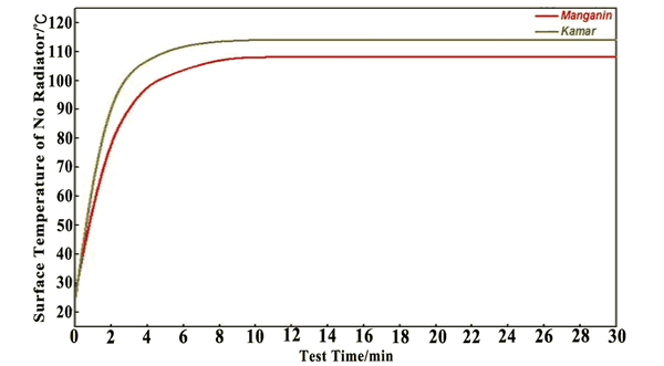
FLM - Surface Temperature Curve |
Low Ohm Chip Resistors (FLM) TCR Derating Curve
|

Alloy Shunt Resistors (FLM) Environmental Characteristics
| Iterms | Requirement | Test Methods |
| Temperature Cycling | ±0.5% | JESD22 1000 Cycles (-55°C to +125°C). Measurement at 24±2 hours after test conclusion. |
| High Temperature Exposure | ±0.5% | MIL-STD-202 1000hrs.@T=125°C.Unpowered. Measurement at 24±2 hours after test conclusion. |
| Moisture Resistance | ±0.5% | MIL-STD-202 t=24hrs/cycle.Note:Steps 7a &anp; 7b not required. Unpowered. Measurement at 24±2 hours after test conclusion. |
| Biased Humidity | ±0.5% | MIL-STD-202 1000hrs 85°C/85%RH.Note: Specified conditions: 10% of operating power. Measurement at 24±2 hours after test conclusion. |
| Operational Life | ±0.5% | MIL-STD-202 Condition D Steady State TA=125°C at rated power. Measurement at 24±2 hours after test conclusion. |
| Solderability | 95% Coverage Minimum. | J-STD-002C 245°C±5°C, 5s+0.5s/-0. |
| Resistance to Soldering Heat | ±0.5% | MIL-STD-202 260°C±5°C,10s±1s. Measurement at 24±2 hours after test conclusion. |
| Short Time Overload | ±0.5% | MIL-STD-202 5×Rated power for 5s. Measurement at 24±2 hours after test conclusion. |
| Thermal Shock | ±1% | MIL-STD-202 -55°C/+125°C, 300 Cycles.Maximumtransfer time 20s, Dwell time 15min. |
| Vibration | ±0.5% | MIL-STD-202 5g's for 20 min, 12 cycles each of 3 orientations. Note: Use 8"X5" PCB .031" thick 7" secure points on one long side and secure points at corners of opposite sides which parts mounted within 2 from any secure point. Test from 10-2000 Hz.Measurement at 24±2 hours after test conclusion. |
Current Shunts (FLM) Derating Curve
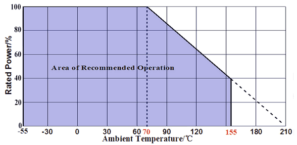
Rated power VS Ambient temperature |
Alloy Shunt Resistors (FLM) Packaging
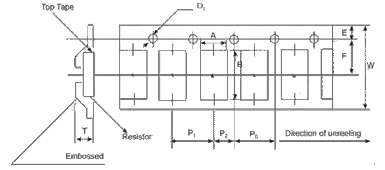
FLM - Embossed Plastic Tape Specif ications |
|||||||||||
| Type | A/mm | B/mm | W/mm | E/mm | F/mm | P0/mm | P1/mm | P2/mm | D0/mm | T/mm | Quantity(EA)/pieces |
| In | 7.5 | 8 | 16 | 1.75 | 7.35 | 6 | 12 | 12 | 1.5 | 3.8 | 3000 |
| Out | 7.3 | 12.1 | 24 | 1.75 | 12.2 | 6 | 12 | 12 | 1.5 | 3.5 | 1000 |
SMD Alloy Current Shunt Resistors (FLM) Order Code
| FLM | - | 5 | M | 0.2 | F | y | ||||||||||||||||||||||||||||||||||||||||||
 | | | | | ||||||||||||||||||||||||||||||||||||||||||||
|
|
|
|
|
|
|||||||||||||||||||||||||||||||||||||||||||