SMD Large Current Weld Precision Resistor Shunts (LRN)
Chip Weld Shunt (LRN) Introduction
SMD High Current Shunt (LRN) with low TCR 20ppm is the first choice for high power circuit design.
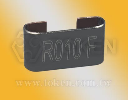
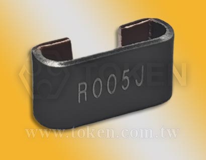
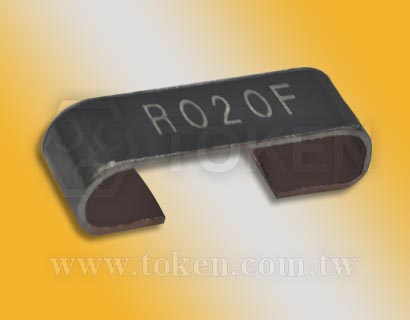
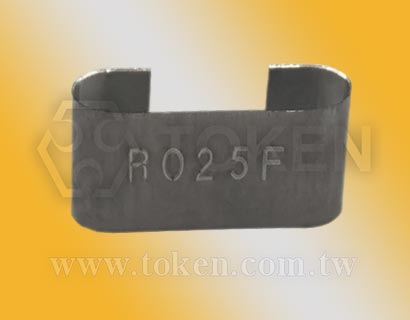
For the development of current detection and shunting applications, TOKEN's high current shunt (LRN) adopts the welding structure of Manganin and KAMAR (NiCr20AlSi) precision resistance alloys.
The spacing standard design makes it easy for surface mounting, reflow soldering, and suitable for current sensing and shunting applications.
Open bare alloy element design allows air flow to achieve maximum cooling effect, so that PCB retains less heat. The design of flame protection structure provides 0.0005Ω low resistance and low inductance. These factors make ruggedness (LRN) an excellent choice for all high current power supply and power applications that are not affected by most environmental stresses.
Specially designed for applications requiring high power processing (LRN). The power is 4W and 7W. The ultra-low resistance ranges from 0.5mΩ to 30mΩ.
There are various tolerance selection advantages (±1%, ±2%, ±5%) , size 4312, and 4320. To achieve compact size and miniaturization, design a smaller, lower cost, higher performance, high power circuit terminal product design.
Provide packing with Embossed Plastic Tape, size 4312 2Kpcs per reel, 4320 2Kpcs per reel, products meet the lead-free and RoHS standards. Customers can specify resistance, size and specifications to meet the design challenges and specific technical requirements. Please contact TOKEN Business Department for the latest product information.
Download complete PDDF specification:Chip Weld Precision Resistors (LRN) PDF.
- Air cooling, Strong stability of circuit.
- Tolerance ±1%, ±2%, and ±5%. Rated Power 4W and 7W.
- Reflow Soldering appliable. lead-free and RoHS compliant.
- TCR down to ±20ppm/°C and ±50ppm/°C. Resistance down to 0.0005Ω.
- Communication system, High current applications for the automotive market.
- Power modules、Frequency converters、Current sensor for power hybrid applications.
Chip Weld Shunts LRN - Dimension Specifications (Unit:mm)
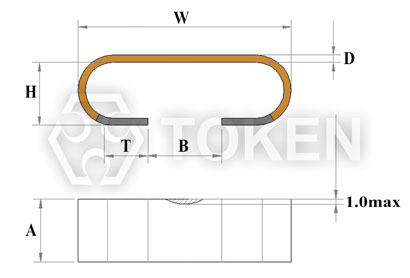
Chip Weld Shunts LRN - Dimensions (Unit:mm) |
||||||||||
| Type | Power (W) | Material | Size | Resistance (mΩ) | D (mm) |
H (mm) |
B (mm) |
W (mm) |
T (mm) |
A (mm) |
| LRN | 4 | M | 4312 | 2 | 0.59±0.05 | 3.1±0.3 | 4.2±0.5 | 11±0.5 | 2.8±0.3 | 3.1±0.3 |
| 3 | 0.39±0.05 | 3.1±0.3 | 4.2±0.5 | 11±0.5 | 2.8±0.3 | 3.1±0.3 | ||||
| 5 | 0.40±0.05 | 3.1±0.3 | 4.2±0.5 | 11±0.5 | 2.8±0.3 | 3.1±0.3 | ||||
| K | 4312 | 10 | 0.62±0.05 | 3.1±0.3 | 4.2±0.5 | 11±0.5 | 2.8±0.3 | 3.1±0.3 | ||
| 20 | 0.62± 0.05 | 3.1± 0.3 | 4.2±0.5 | 11±0.5 | 2.8±0.3 | 3.1±0.3 | ||||
| 30 | 0.25± 0.05 | 3.1± 0.3 | 4.2±0.5 | 11±0.5 | 2.8±0.3 | 3.1±0.3 | ||||
| 7 | M | 4320 | 0.5 | 0.74±0.05 | 3.1±0.3 | 4.2±0.5 | 11±0.5 | 2.8±0.3 | 6.1±0.4 | |
| 1 | 0.37±0.05 | 3.1±0.3 | 4.2±0.5 | 11±0.5 | 2.8±0.3 | 6.1±0.4 | ||||
| 5 | 0.20±0.05 | 3.1±0.3 | 4.2±0.5 | 11±0.5 | 2.8±0.3 | 6.1±0.4 | ||||
| K | 4320 | 5 | 0.62±0.05 | 3.1±0.3 | 4.2±0.5 | 11±0.5 | 2.8±0.3 | 6.1±0.4 | ||
| 10 | 0.30±0.05 | 3.1±0.3 | 4.2±0.5 | 11±0.5 | 2.8±0.3 | 6.1±0.4 | ||||
| 15 | 0.20±0.05 | 3.1±0.3 | 4.2±0.5 | 11±0.5 | 2.8±0.3 | 6.1±0.4 | ||||
Chip Weld Resistors LRN - Surface Temperature Curve
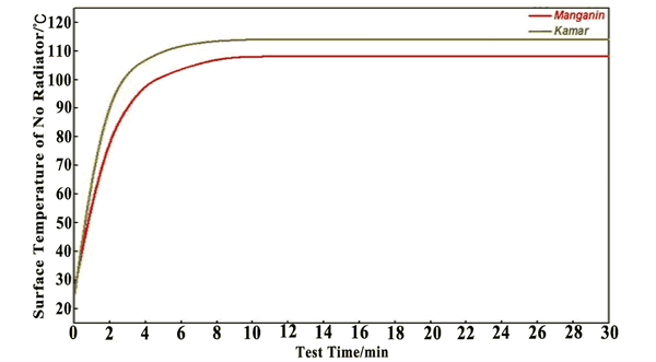
Surface Temperature Curve (LRN) |
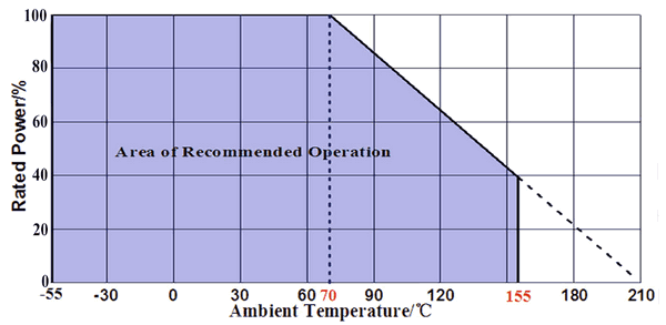
SMD Weld Resistors LRN - TCR Derating Curve

TCR Derating Curve (LRN) |
SMD Weld Resistor LRN - Environmental Characteristics
| Iterms | Requirement | Test Methods |
|---|---|---|
| Temperature Cycling | ±0.5% | JESD22 1000 Cycles (-55°C to +125°C). Measurement at 24±2 hours after test conclusion. |
| High Temperature Exposure | ±0.5% | MIL-STD-202 1000hrs.@T=125°C. Unpowered. Measurement at 24±2 hours after test conclusion. |
| Moisture Resistance | ±0.5% | MIL-STD-202 t=24 hrs/cycle. Note:Steps 7a & 7b not required.Unpowered. Measurement at 24±2 hours after test conclusion. |
| Biased Humidity | ±0.5% | MIL-STD-202 1000hrs 85°C/85% RH. Note: Specified conditions:10% of operating power. Measurement at 24±2 hours after test conclusion. |
| Operational Life | ±0.5% | MIL-STD-202 Condition D Steady State TA=125°C at rated power. Measurement at 24±2 hours after test conclusion. |
| Solderability | 95% Coverage Minimum. | J-STD-002C 245°C±5°C, 5s+0.5s/-0. |
| Resistance to Soldering Heat | ±0.5% | MIL-STD-202 260°C±5°C, 10s±1s. Measurement at 24±2 hours after test conclusion. |
| Short Time Overload | ±0.5% | MIL-STD-202 5 × Rated power for 5s. Measurement at 24±2 hours after test conclusion. |
| Thermal Shock | ±1% | MIL-STD-202 -55°C/+125°C, 300 Cycles.Maximumtransfer time 20s, Dwell time 15min. |
| Vibration | ±0.5% | MIL-STD-202 5g's for 20 min, 12 cycles each of 3 orientations. Note: Use 8"X5" PCB .031" thick 7" secure points on one long side and secure points at corners of opposite sides which parts mounted within 2 from any secure point. Test from 10-2000 Hz. Measurement at 24±2 hours after test conclusion. |
LRN - Derating Curve
Rated power VS Ambient temperature (Power Derating Cruve) |
LRN - Packaging
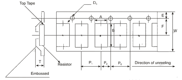
LRN - Embossed Plastic Tape Specifications |
|||||||||||
| Size | A/mm | B/mm | W/mm | E/mm | F/mm | P0/mm | P1/mm | P2/mm | D0/mm | T/mm | Quantity (EA) / pieces |
| 4312 | 4.3 | 12.5 | 24 | 1.55 | 7.5 | 6 | 12 | 12 | 1.50 | 3.8 | 2000 |
| 4320 | 7 | 12.5 | 24 | 1.55 | 11.2 | 6 | 12 | 12 | 1.50 | 3.8 | 1000 |
SMD Large Current Weld Precision Shunts LRN - Order Code
| LRN | - | 4 | - | M | - | R003 | - | J | ||||||||||||||||||||||||||||||||||
|---|---|---|---|---|---|---|---|---|---|---|---|---|---|---|---|---|---|---|---|---|---|---|---|---|---|---|---|---|---|---|---|---|---|---|---|---|---|---|---|---|---|---|
 |
|
|
|
|
||||||||||||||||||||||||||||||||||||||
|
|
|
|
|
||||||||||||||||||||||||||||||||||||||