Metal Alloy Zero Ohm Jumper Chip Resistors (LRJ)
Zero Ohm Jumper link Resistors (LRJ) Introduction
New Performance Requirements for True Metal Alloy Zero Ohm Jumper Chip Resistor in High Power Applications.
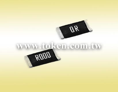
A zero ohm resistor is often called SMD jumper resistors, milli-ohm resistor, or zero ohm link resistors which are designed to link to circuits to together just like any other wire.
Token's true metal alloy strip zero ohm resistors (LRJ) make options with a lot less space and cost than DIP switches and jumper headers. These high current metal alloy jumper resistor chips (LRJ) SMT series, designed to replace zero ohm resistors without changing board designs or layouts.The devices could also be applied in high power applications to replace jumper wire for better stability or buried copper coin PCB for cost saving.
Five jumpers for the different resistor chip sizes are provided a wide range of standard dimensions 1206, 2512, 2817, 2725, and 4527 to make ease of designs along with footprint template compatibility. Token (LRJ) SMD metal alloy current jumper resistors designed for applications that require high power handling (Up to 5W) with resistance < 0.2mΩ at operating temperature range -55°C~+150°C. (LRJ). These new products are distinctively suited as true zero ohm resistor replacements.
Token (LRJ) resistor chip jumpers manufactured from metal alloy plate and designed to deliver a extremely low impedance and profile circuit linkage as a zero ohm resistor. Chip jumpers are packaged on tape and reel for compatibility with most vacuum or mechanical pick and place assembly systems. These (LRJ) SMD devices are also suitable for high current, high-density PCB packages on power and aluminum backplanes.
Some circuit boards are designed with multiple functions and configurations in one design. Often these functions and configurations can't coexist in single circuit because they will conflict with each other. To this end, more and more designers use (LRJ) resistor SMD jumpers for single side PCB that has no through-hole but for double-sided PCB. An application is used as a dummy, when through-holes for a not- yet- designed- resistor are prepared by way of precaution, and the holes are short-circuited after all.
Token electronics delivers the right chip for your low range, current-sense applications. For more detailed product information and data sheets or to discuss your specific requirements please contact Token electronics. Downloads Complete Specification PDF Metal Alloy Zero Ohm Jumper link Resistors (LRJ).
- High current application with Low profile.
- Ultra-Low resistance values, 0.2mΩ Max.
- operating temperature range -55°C~+150°C.
- Wide range package sizes 1206, 2512, 2817, 2725, and 4527.
- Electrical tools, Power Management
- NB, Mobil Device, Server, Portable Devices
- Automotive, Industrial, Consumer Electronics, Electric Instrument
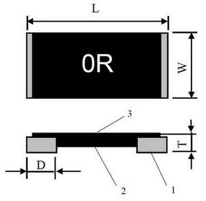
Zero Ohm Resistors (LRJ) - Construction & Dimensions
Zero Ohm Jumper link Resistors (LRJ) |
|||||||||||
| 1 | Solder Plating (Sn) |
| 2 | Alloy Plate |
| 3 | Overcoat |
| Type | Power Rating at 70℃(W) | Dimensions (Unit: mm) | |||
| L | W | T | D | ||
| LRJ1206 | 1 | 3.200±0.254 | 1.650±0.254 | 0.670±0.254 | 0.508±0.254 |
| LRJ2512 | 2 | 6.350±0.254 | 3.050±0.254 | 0.670±0.254 | 1.100±0.254 |
| LRJ2817 | 3 | 7.100±0.254 | 4.200±0.254 | 0.770±0.254 | 1.500±0.254 |
| LRJ2725 | 4 | 6.800±0.254 | 6.350±0.254 | 0.770±0.254 | 1.800±0.254 |
| LRJ4527 | 5 | 11.300±0.500 | 6.600±0.500 | 0.770±0.254 | 2.000±0.254 |
Zero Ohm Chips (LRJ) - Electrical Specifications
| Type | Power Rating at 70°C | Max. Rating Current (A)* | Resistance (mΩ) | Operating Temperature °C |
| LRJ1206 | 1 | 70.7 | < 0.2 | -55~+150°C |
| LRJ2512 | 2 | 100 | < 0.2 | |
| LRJ2817 | 3 | 122 | < 0.2 | |
| LRJ2725 | 4 | 140 | < 0.2 | |
| LRJ4527 | 5 | 158 | < 0.2 |
- Note: Rating Current I=√ ( P / R ) or Max. Rating Current whichever is lower.
- Special tolerance and range of resistance are under requested.
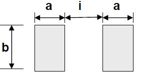
Zero Ohm Chips (LRJ) Recommend Land Pattern
 Zero Ohm Chips (LRJ) Recommend Land Pattern |
|||||
| Type | Maximum Power Rating (Watts) | Dimensions (Unit: mm) | |||
| a | b | i | |||
| LRJ1206 | 1 | 1.00 | 1.90 | 1.40 | |
| LRJ2512 | 2 | 2.11 | 3.68 | 3.18 | |
| LRJ2817 | 3 | 2.45 | 4.60 | 3.11 | |
| LRJ2725 | 4 | 2.34 | 6.86 | 3.00 | |
| LRJ4527 | 5 | 3.40 | 8.74 | 6.43 | |
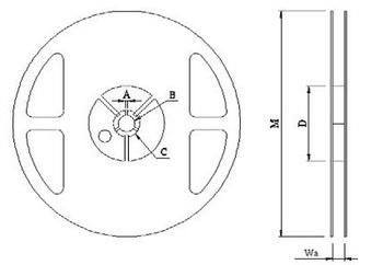
Reel Specifications (LRJ) (Unit: mm)
Reel Dimensions (Unit: mm) |
||||||||
| Reel Type / Tape | W | M | A | B | C | D | ||
| 7” reel for 8 mm embossed (LRJ1206 series only) |
12.00± 0.5 | 178 ± 1.0 | 2.0 ± 0.5 | 13.2 ± 0.5 | 17.7 ± 0.5 | 60.0 ± 0.5 | ||
| 7” reel for 12 mm embossed LRJ2512, LRJ2725, LRJ2817 |
16.2 ± 0.5 | 178 ± 1.0 | 2.5 ± 0.5 | 13.5 ± 0.5 | 17.7 ± 0.5 | 60.0 ± 0.5 | ||
| 7” reel for 24 mm embossed (LRJ4527 series only) |
24.4 +2/-0 | 178 ± 1.0 | 2.0 ± 0.5 | 13.2 ± 0.5 | 17.7 ± 0.5 | 60.0 ± 0.5 | ||
Emboss Plastic Tape Specifications (LRJ) (Unit: mm)
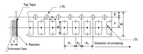 Emboss Plastic Tape Specifications (Unit: mm) |
||||||||||||
| Type | A±0.1 | B±0.1 | W±0.3 | E±0.1 | F±0.1 | P0±0.1 | P1±0.3 | P2±0.1 | ΦD0±0.05 | ΦD1±0.1 | T±0.1 | |
| LRJ1206 | 2.03 | 3.55 | 8.0 | 1.75 | 3.5 | 4.0 | 4.0 | 2.0 | 1.55 | 1.00 | 1.00 | |
| LRJ2512 | 3.50 | 6.75 | 12.0 | 1.75 | 5.5 | 4.0 | 4.0 | 2.0 | 1.55 | 1.55 | 0.90 | |
| LRJ2725 | 6.81 | 7.16 | 12.0 | 1.75 | 5.5 | 4.0 | 8.0 | 2.0 | 1.55 | 1.55 | 1.05 | |
| LRJ2817 | 4.60 | 7.50 | 12.0 | 1.75 | 5.5 | 4.0 | 8.0 | 2.0 | 1.55 | 1.55 | 1.20 | |
| LRJ4527 | 7.38 | 12.0 | 24.0 | 1.75 | 11.5 | 4.0 | 12.0 | 2.0 | 1.55 | 1.55 | 1.05 | |
- The cumulative tolerance of 10 sprockets hole pitch is ± 0.2mm.
- Carrier camber shall be not more than 1mm per 100mm through a length of 250mm.
- A & B measured 0.3mm from the bottom of the packet
- T measured at a point on the inside bottom of the packet to the top surface of the carrier.
- Pocket position relative to sprocket hole is measured as the true position of the pocket and not the pocket hole.
Packaging Quantity (LRJ)
| Type | Tape Width | Diameter | Piece/Reel |
| LRJ1206 | 8 mm/embossed plastic | 178 mm/7” | 5,000 |
| LRJ2512 | 12 mm/embossed plastic | 178 mm/7” | 4,000 |
| LRJ2725 | 12 mm/embossed plastic | 178 mm/7” | 2,000 |
| LRJ2817 | 12 mm/embossed plastic | 178 mm/7” | 1,000 |
| LRJ4527 | 24 mm/embossed plastic | 178 mm/7” | 1,000 |
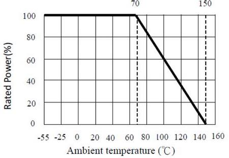
Derating Curve (LRJ)
 |
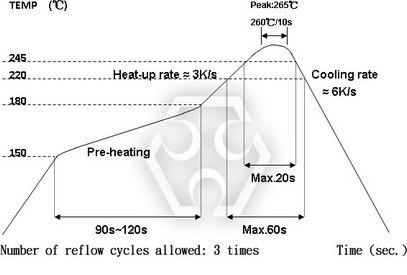
Soldering Condition (Reflow Only) (LRJ)
 |
Environmental Characteristics (LRJ)
| Item | Requirement | Test Method |
| Short Time Overload |
≤0.2 mΩ
|
JIS C 5201-1 4.13 4 times rated power duration: 5secs. |
| Load Life |
≤0.2 mΩ
|
JIS-C5201-1 4.25 70±2°C, RCWV for 1000 Hrs. with 1.5 Hrs. “ON” and 0.5 Hr. “OFF” |
| Bias Humidity |
≤0.2 mΩ
|
JIS-C5201-1 4.24 +85°C/85%RH for 1,000Hrs. with 1.5Hrs “ON”, 0.5Hr “OFF”. |
| High Temperature Exposure (Storage) |
≤0.2 mΩ
|
JIS-C5201-1 4.23.2 +150°C for 1000 Hrs. |
| Solderability |
95% Min. coverage
|
JIS-C5201-1 4.17 245±5°C for 3 seconds |
| Temperature Cycling |
≤0.2 mΩ
|
JIS-C5201-1 4.19 -55°C ~ 150°C, 100 cycles |
Order Codes (LRJ)
| LRJ | 1206 | TR | T | R000 | ||||||||||||||||||||||||||||||||||
 |
|
|
|
|
||||||||||||||||||||||||||||||||||
|
|
|
|
|
||||||||||||||||||||||||||||||||||