Power Metal Film Flame-Proof Resistors (FMF)
(FMF) Non-Flammable Metal Film Resistor - Introduction
Flame Proof Resistor (FMF), low TCR, low noise and high precision for telecommunication, comsumer products.
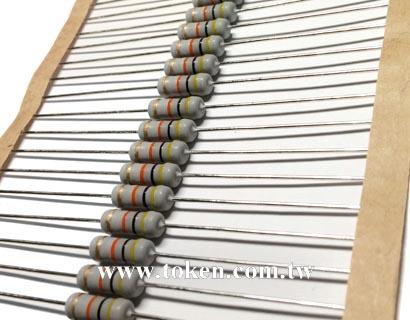
Token Electronics is a global engineering electronics supplier for performance-critical applications, introducing the (FMF) series of Power Metal Film Flame-Proof Resistors. Offering a combination of high precision and handling high power conditions, this resistor is ideal for measuring power line voltage for power condition and energy metering monitoring.
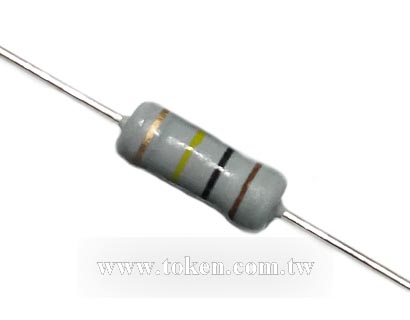
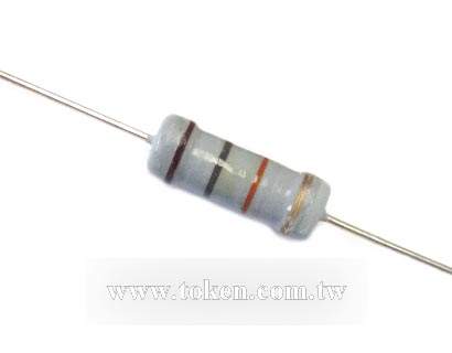
Token (FMF) Flame-Proof Resistor is desogned to provide an alternative options between Power Metal Oxide Resistors (RSS, RSN) and Precision Metal-Film Resistors (MF). The (FMF) takes the power handling with flame-proof advantage of metal oxide resistors and inherits the precision tolerance of (MF) metal film resistors to provide a solution for customers looking for an industrial grade flame-proof resistors.
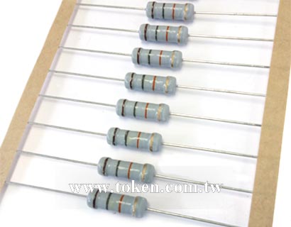
The power of Flame-Proof Resistor (FMF) is rated at 1/4, 1/2WS, 1/2W, 1W, 2WS, 2W, 3WS, 3W, 5WS, 5W, and 7WS respectively. Standard values from 0.1Ω to 10MΩ are available, E24, E-96, and E-192 nominal standard series provides adequate "‘close value match" choice for designers. Maximum overload voltage specifies up to 1000V at 5W normal size or 7WS minimum size.
The (FMF) resistors have excellent high power characteristics to improve reliability and reduce faults. With precision levels of ±0.1% resistance tolerance and ±15ppm/°C TCR they free up designers’ error budgets, enabling savings elsewhere in the circuit. Accuracy is ± 0.1%, ± 0.25%, ± 0.5%, ± 1%, ± 2%, and ± 5% precision tolerance, which saves the designer's error budget and free up other parts of the circuit.
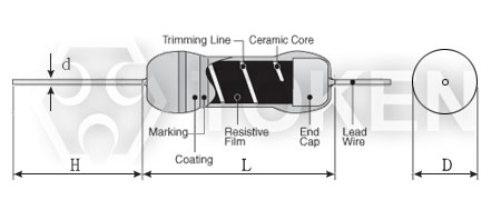
Structurally the resistors include a homogeneous sputtered metal alloy film on a high-aluminum ceramic rod and protect with flame-proof coating. The resistance value in the film was adjusted to the final value by laser spiral cutting. The terminals on both ends of the resistor are covered with a pure tin coating to avoid aging the contacts and a low melting point solder can be used thereon.
Download Metal Film Non-Flammable Resistor (FMF) in PDF.
- Power Supplies, Telecommunications.
- Computer, Household Appliances, Automotive.
- Amplifiers, Test Equipment and Instrumentation.
- Precision Controls, Ballasts, Medical Equipment, Security Monitoring.
- High power in small packages, Low electrical noise.
- Outstanding stability under a wide range of electrical and environmental stresses.
- Pure tin plating provides compatibility with lead (Pb)-free and lead containing soldering processes.
- Compatible with “Restriction of the use of Hazardous Substances” (RoHS) directive 2011/65/EU.
(FMF) Specifications & Dimensions (Unit: mm)
Specifications & Dimensions (Unit: mm) (FMF) |
||||||||||||
| Style FMF |
Dimensions (Unit: mm) | Operating Temp. Range (°C) | Max Working Voltage (V) | Max Overload Voltage (V) | ||||||||
| Normal | Mini | L | D | H | d ± 0.1 | Normal | Mini | Normal | Mini | |||
| 1/4W | 1/2WS | 6.3±0.5 | 2.3±0.3 | 28±2.0 | 0.55 | -55 ~ +155 | 300 | 200 | 500 | 400 | ||
| 1/2W | 1WS | 9.0±1.0 | 3.2±0.5 | 26±3.0 | 0.65 | 350 | 250 | 600 | 500 | |||
| 1W | 2WS | 11.5±1.0 | 4.5 ±0.5 | 33 ±3.0 | 0.78 | 350 | 300 | 700 | 600 | |||
| 2W | 3WS | 15.5±1.0 | 5.0±0.5 | 32±3.0 | 0.78 | 350 | 350 | 700 | 700 | |||
| 3W | 5WS | 17.5±1.0 | 6.5±0.5 | 35±3.0 | 0.78 | 500 | 350 | 1000 | 700 | |||
| 5W | 7WS | 24.5±1.0 | 8.5±0.5 | 35±3.0 | 0.78 | 600 | 500 | 1000 | 800 | |||
- The maximum value of D.C. voltage or A.C. voltage (commercial frequency effective value) capable of being applied continuously to resistors at the rated ambient temperature.
- Rated voltage shall be calculated from the following formula. However, it shall not exceed the maximum working voltage.
- Rated Voltage (RCWV) = √Rated Power (W) x Nominal Resistance Value (Ω)
(FMF) Resistance & TCR Range
| Style | Tolerance (%) | TCR (ppm/°C)/ Ω | |||||
| Normal | Mini | ±15 | ±25 | ±50 | ±100 | ±200 | |
| 1/4W | 1/2WS | ±5% | 0.1Ω~10MΩ | ||||
| ±2% | 0.1Ω~10MΩ | ||||||
| ±1% | 10Ω~1MΩ | 10Ω~10MΩ | 10Ω~10M | 0.1Ω~10MΩ | 0.1Ω~10MΩ | ||
| ±0.5% | 10Ω~1MΩ | 10Ω~10MΩ | 10Ω~10M | 0.1Ω~10MΩ | |||
| ±0.25% | 10Ω~1MΩ | 10Ω~1MΩ | 10Ω~1MΩ | 0.1Ω~1MΩ | |||
| ±0.1% | 10Ω~1MΩ | 10Ω~1MΩ | 10Ω~1MΩ | ||||
| 1/2W | 1WS | ±5% | 0.1Ω~10MΩ | ||||
| ±2% | 0.1Ω~10MΩ | ||||||
| ±1% | 10Ω~1MΩ | 10Ω~10MΩ | 0.1Ω~10MΩ | 0.1Ω~10MΩ | |||
| ±0.5% | 10Ω~1MΩ | 10Ω~10MΩ | 0.1Ω~10MΩ | ||||
| ±0.25% | 10Ω~1MΩ | 10Ω~1MΩ | 0.1Ω~1MΩ | ||||
| ±0.1% | 10Ω~1MΩ | 10Ω~1MΩ | |||||
| 1W | 2WS | ±5% | 0.1Ω~10M | ||||
| ±2% | 0.1Ω~10M | ||||||
| ±1% | 10Ω~1MΩ | 10Ω~10MΩ | 0.1Ω~10MΩ | 0.1Ω~10M | |||
| ±0.5% | 10Ω~1MΩ | 10Ω~10MΩ | 0.1Ω~10MΩ | ||||
| ±0.25% | 10Ω~1MΩ | 10Ω~1MΩ | 0.1Ω~1MΩ | ||||
| ±0.1% | 10Ω~1MΩ | 10Ω~1MΩ | |||||
| 2W | 3WS | ±5% | 0.1Ω~10MΩ | ||||
| ±2% | 0.1Ω~10MΩ | ||||||
| ±1% | 10Ω~1MΩ | 10Ω~10MΩ | 0.1Ω~10MΩ | 0.1Ω~10MΩ | |||
| ±0.5% | 10Ω~1MΩ | 10Ω~10MΩ | 0.1Ω~10MΩ | ||||
| ±0.25% | 10Ω~1MΩ | 10Ω~1MΩ | 0.1Ω~1MΩ | ||||
| ±0.1% | 10Ω~1MΩ | 10Ω~1MΩ | |||||
| 3W | 5WS | ±5% | 0.1Ω~10MΩ | ||||
| ±2% | 0.1Ω~10MΩ | ||||||
| ±1% | 0.1Ω~100KΩ | 0.1Ω~10MΩ | |||||
| ±0.5% | 10Ω~100KΩ | ||||||
| 5W | 7WS | ±5% | 0.1Ω~100KΩ | ||||
| ±2% | 0.1Ω~100KΩ | ||||||
| ±1% | 0.1Ω~100KΩ | 0.1Ω~100KΩ | |||||
| ±0.5% | 10Ω~100KΩ | ||||||
| * Resistance standard decade values E-24, E-96, E-192. | |||||||
(FMF) Electrical Performance
| Test Characteristics | Test Methods | Performance Requirement |
| Resistance | Measuring points at 10mm±1mm from the end cap. | Within regulated tolerance |
| T.C.R. | Room temperature /100°C up. | ± 15, ± 25, ± 50, ± 100,± 200ppm/°C |
| Short Time Overload | Rated voltageX2.5 or Max. overload voltage for 5s whichever less. | ±(2%+0.1Ω) |
| Solderability | 260°C±5°C, 2s±0.5s | 90% Coverage Min. |
| Terminal strength | Direct load: 25N, 10s Twist test:360°, 5 times Bending test:5N, 90°, 2 times |
No mechanical damages |
| Moisture resistance | 40°C±2°C, 90%~95%RH, 1000Hrs, 1.5Hrs on/0.5Hr off cycle | ±(5%+0.1Ω) |
| Load Life | 70°C±2°C, 1000Hrs, 1.5Hr on/0.5Hr off cycle. | ±(5%+0.1Ω) |
(FMF) Hot-Spot Temperature
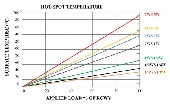
Flame-Proof Resistor (FMF) Hot-Spot Temperature |
(FMF) Derating Curve
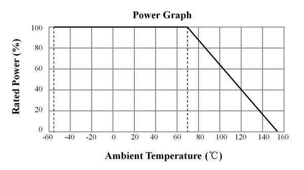
Non-flammable Resistor (FMF) Derating Curve |
(FMF) Order Codes
| FMF | 1/2W | 100R | J | T52 | |||||||||||||||||||||||||||||||||||||||||||||||||||||||||||
 |
|
|
|
|
|
||||||||||||||||||||||||||||||||||||||||||||||||||||||||||
|
|
|
|
|
|
||||||||||||||||||||||||||||||||||||||||||||||||||||||||||