Zero Ohm Resistors & Jumper Wire (ZO, JW)
(ZO, JW) Jumper Wire Zero Ohm Resistor - Introduction
A Quick Solution to PCB Board Connections
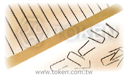
Jumper Wire (JW series a zero-ohm link) and zero-ohm resistor (ZO series) are a link used to connect traces on a printed circuit board that is packaged in the same format as a resistor.
The resistance of JW and ZO series is only approximately zero; only a maximum 0.05Ω is specified. Thus, a fractional tolerance (as a percentage of the zero-ohm ideal value) would be infinite and is not specified.
Axial through-hole zero-ohm resistors are especially suited for automatic machine insertion and generally marked with a single black band.
Allowing customers to standardise on the PCB layout and use jumper wire and zero ohm resistor for required model variations, Token has developed a wider version for the interconnection device between points on a PCB board as jumper wires or crossovers. Contact us with your specific needs.
Downloads Complete Specification PDF Zero Ohm Resistors & Jumper Wire (ZO, JW).
- Ideal straight - through between point on PC Boards.
- Maximum resistance 0.05Ω, RoHS compliant with 100% lead free.
- Lead Material: Tin-plated copper lead, Packing: Tape/Reeled or Bulk.
- Interrupt processing, Input and output distribution.
- Ideal connection for circuit boards, Dummy components on a PCB test board.
- Circuit tuning by changing point connections.
- An "after the fact design" the requires new point connections.
- Inability to connect two points on a PCB board due to other circuit paths which must be crossed over.
(ZO)Zero Ohm Resistor - General Specification (Unit: mm)
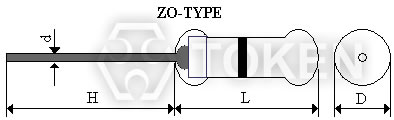
Zero Ohm Resistors (ZO) Dimensions |
|||||
| Type | Rating | Dimension (mm) | |||
| L Max. | D Max. | H ± 3 | d+0.02-0.04 | ||
| ZO - 1/8 | 0.125W | 4.2 | 2.0 | 28 | 0.5 |
| ZO- 1/4 | 0.25W | 6.8 | 2.5 | 28 | 0.5 |
(JW) Jumper Wire - General Specification (Unit: mm)
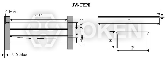
Taping Jumper Wire (JW) Dimensions |
||||
| Type | L±1 | d+0.02 -0.04 | H | P |
| JW-A | 61.5 | 0.5 | 3 - 10 | 5 - 30 |
| JW-B | 61.5 | 0.6 | 3 - 10 | 5 - 30 |
Construction & Dimensions (Unit: mm) Jumper Wire Forming (JW)
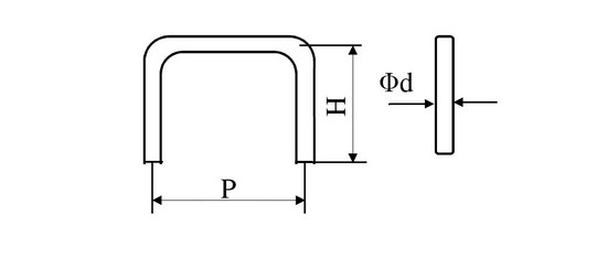
Forming Jumper Wire (JW) Construction |
||||
| ITEM | Φd | P | H | |
| JW-B-M-5×5×5 | 0.6±0.05 | 5±1.0 | 5±1.0 | |
| JW-B-M-8×5×8 | 0.6±0.05 | 5±1.0 | 8±1.0 | |
Electrical Characteristics Jumper Wire (JW)
| Requirements | Characteristics |
| Current Rating | 6 AMPS at 70°C |
| Conductor Resistance | 0.54mΩ/cm |
| Material | Tin-plated copper |
| Element of Plating | Tin 99.9~100%, Lead 0~0.01% Max. |
| Thickness of Plating | 5μ±2μ |
| Solder ability | 260±5, 3sec. Coverage 95% |
| Conductivity | 96% Min. |
| Tensile | 26 Kg/mm2 Max. |
| Elongation | 20% Min. |
(ZO, JW) Electrical Performance
| Requirements | Characteristics |
| Maximum Resistance | 0.05Ω |
| Lead Material | tin-plead copper |
| Body Material | Electrical grade, high performance molding compound |
| Dielectric Withstanding Voltage | Atomspheric-500V RMS, Reduced-325V RMS |
| Insulation Flammability | Resistor Insulation is self extinguishing within 10 seconds after externally applied flame is removed. |
| Current Rating | 25 AMPS at 25°C, dreading to 0 AMPS at 150°C |
(ZO, JW) Zero Ohm Resistor & Jumper Wire - Order Codes
| ZO-1/4 | 0.25W | TB | ||||||||||||||
 |
|
|
||||||||||||||
|
|
|
||||||||||||||
(JW) Forming Jumper Wire - Order Codes
| JW | B | M | 5×5×5 | |||||||||||
|
|
|
|
|||||||||||
|
|
|
|
|||||||||||
- Package Information of Jumper Wire Forming: Bulk Type, 5KPcs/Bag/Box.