SMD Ceramic Resonators 1.79 ~ 50.00 MHz (ZTAC/ZTTC)
SMD MHz Ceramic Resonators (ZTAC/ZTTC) Introduction
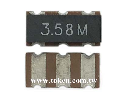
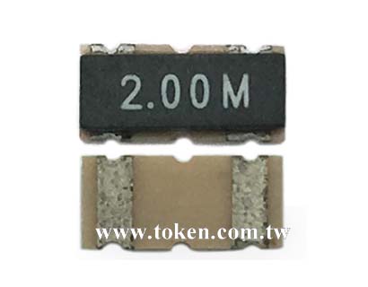
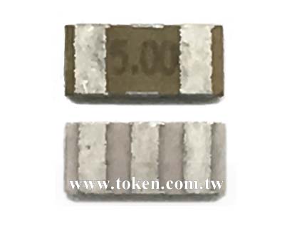
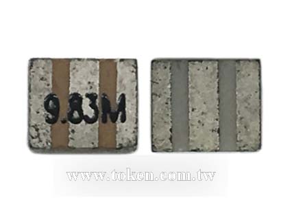
Token (ZTAC/ZTTC) series is the smallest surface mount ceramic resonators (Murata resonator CSAC/CSTC compatible).

Previously, only higher cost quartz crystal resonators were considered for CAN bus application, due to tighter frequency tolerance requirements than for traditional automotive bus applications. Nowaday, Token utilizes the latest ceramic piezo technology freeing the design engineers from having to use these higher cost components and still achieve desired reliability and performance targets.
Token ZTAC and ZTTC series are the SMD ceramic resonators that meet the frequency tolerance ±0.5%, temperature tolerance ±0.3% ~ ±0.4%, and aging tolerance ±0.3%. The ZTAC and ZTTC covers the frequency range of 1.79 MHz to 50.00 MHz. ZTTC series features a built-in load capacitance. This feature eliminates any need for external loading capacitors and reduces component count, increases reliability and reduces size.
The ZTACE×MG (3.2 x 1.3 mm) with (max) profile 1.0 mm and ZTACW×MX (2.5 x 2.0 mm) with (max) profile 1.5 mm are the smallest resonators for their respective frequency ranges. All ZTAC and ZTTC series are surface mount devices (SMD) with operating temperature range is -20°C to +80°C.
Tolerance is the main key characteristics to evaluate for a resonator. The total tolerance is the addition of the initial tolerance, temperature tolerance and aging tolerance. Tighter tolerances are possible through design advancements, material refinement and manufacturing techniques. Token's design and material improve the temperature and aging characteristics of the resonator. Token's manufacturing ability sort to tighter initial tolerances.
Custom parts are available on request. Token will also produce devices outside these specifications to meet specific customer requirements, please contact Token sales for more information.
Download complete datasheet SMD MHz Ceramic Resonators (ZTAC/ZTTC) PDF.
- High reliability chip resonator with high temperature withstanding ceramic case.
- Ultra-miniature size is suitable for compact equipment high mounting density.
- Low profile, Reflow solderable, Excellent solderability.
- Car accessories.
- PDAs, PC peripherals.
- Camcorders, Digital cameras.
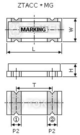
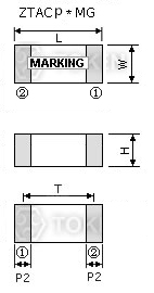
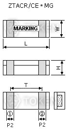
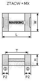
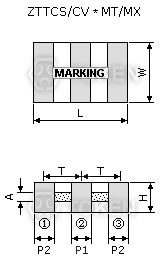
Dimensions (ZTAC)
|
|||||||
| Part Number | Dimensions (Unit: mm) | ||||||
| L | W | H | P2 | T | |||
| ZTACC*MG | 7.4±0.2 | 3.4±0.2 | 1.8±0.2 | 1.2±0.2 | 5.0±0.3 | ||
| ZTACP*MG | 6.0±0.2 | 3.0±0.2 | 2.0 Max. | 1.2±0.2 | 5.0±0.3 | ||
| ZTACR*MG | 4.5±0.2 | 2.0±0.2 | 1.2 Max. | 0.8±0.2 | 3.0±0.2 | ||
| ZTACE*MG | 3.2±0.1 | 1.3±0.1 | 1.0 Max. | 0.4±0.1 | 2.4±0.1 | ||
| ZTACS*MT/MX | 4.7±0.2 | 4.1±0.2 | (1.2+A)±0.2 | 0.8±0.2 | 3.9±0.2 | ||
| ZTACV*MT/MX | 3.7±0.2 | 3.1±0.2 | (1.0+A)±0.2 | 0.7±0.2 | 3.0±0.2 | ||
| ZTACW*MX | 2.5±0.2 | 2.0±0.2 | 1.5 Max. | 0.4±0.2 | 2.0±0.2 | ||


Note : A stands for thickness of the ceramic element, which varies with the frequency. The range of the thickness is 0.1 to 0.7mm.
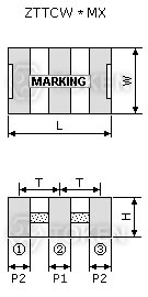
Dimensions (ZTTC)
|
||||||||
| Part Number | Dimensions (Unit: mm) | |||||||
| L | W | H | P1 | P2 | T | |||
| ZTTCC*MG | 7.4±0.2 | 3.4±0.2 | 1.8±0.2 | 1.2±0.2 | 1.2±0.2 | 2.5±0.3 | ||
| ZTTCP*MG | 6.0±0.2 | 3.0±0.2 | 2.0 Max. | 1.2±0.2 | 1.2±0.2 | 2.5±0.3 | ||
| ZTTCR*MG | 4.5±0.2 | 2.0±0.2 | 1.2 Max. | 0.8±0.2 | 0.8±0.2 | 1.5±0.2 | ||
| ZTTCE*MG | 3.2±0.1 | 1.3±0.1 | 1.0 Max. | 0.4±0.1 | 0.4±0.1 | 1.2±0.1 | ||
| ZTTCS*MT/MX | 4.7±0.2 | 4.1±0.2 | (1.2+A)±0.2 | 1.0±0.2 | 0.8±0.2 | 1.95±0.2 | ||
| ZTTCV*MT/MX | 3.7±0.2 | 3.1±0.2 | (1.0+A)±0.2 | 0.9±0.2 | 0.7±0.2 | 1.5±0.2 | ||
| ZTTCW*MX | 2.5±0.2 | 2.0±0.2 | 1.5 Max. | 0.5±0.2 | 0.4±0.2 | 1.0±0.2 | ||

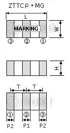


Note : A stands for thickness of the ceramic element, which varies with the frequency. The range of the thickness is 0.1 to 0.7mm.
Technical Characteristics (ZTAC/ZTTC)
| Part Number | Frequency Range (MHz) |
Frequency Accuracy (%) |
Stability in Temperature (-20°C ~ +80°C) (%) |
Aging for Ten Years (%) |
| ZTACC*MG / ZTTCC*MG | 2.00 ~ 12.00 | ± 0.5 | ± 0.3 | ± 0.3 |
| ZTACP*MG / ZTTCP*MG | 1.79 ~ 8.00 | ± 0.5 | ± 0.3 | ± 0.3 |
| ZTACR*MG / ZTTCR*MG | 4.00 ~ 8.00 | ± 0.5 | ± 0.3 | ± 0.3 |
| ZTACS*MT / ZTTCS*MT | 6.00 ~ 13.00 | ± 0.5 | ± 0.4 | ± 0.3 |
| ZTACV*MT / ZTTCV*MT | 8.00 ~ 13.00 | ± 0.5 | ± 0.4 | ± 0.3 |
| ZTACE*MG / ZTTCE*MG | 8.00 ~ 13.00 | ± 0.5 | ± 0.4 | ± 0.3 |
| ZTACS*MX / ZTTCS*MX | 13.01 ~ 50.00 | ± 0.5 | ± 0.3 | ± 0.3 |
| ZTACV*MX / ZTTCV*MX | 16.00 ~ 50.00 | ± 0.5 | ± 0.3 | ± 0.3 |
| ZTACW*MX / ZTTCW*MX | 20.00 ~ 45.00 | ± 0.5 | ± 0.3 | ± 0.3 |
Test Circuit for MOS IC (ZTAC/ZTTC)
 MHz (ZTTC) Test Circuit for MOS IC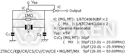 MHz (ZTAC) Test Circuit for MOS IC |
(ZTAC/ZTTC) Resonator Application - Oscillation Circuit for MOS IC
Feedback Resistor (R = 1MΩ):
A Feedback Resistor is used to determine the oscillation circuit bias. The feedback resistance will contribute to instability if it is too large by reducing feedback. Conversely, if it is too small, increases in current will be realized thereby reducing gain. Recent developments in IC design allows for the integration of the feedback resistor in many cases.
Bias resistor (Rb optional):
A Bias Resistor can be utilized in the resonator oscillation circuit to change the bias point when a reduction in IC gain is required, or to suppress unstable oscillation. This may be especially considered when a 3 stage buffered IC, or TTL IC, is used.
Damping Resistor (Rd optional):
Abnormal harmonic oscillation can be suppressed using a dampening resistor. The dampening resistor and load capacitors work together as a low-pass filter to reduce gain in the MHz range of oscillation.
Loading Capacitor (C1 & C2)
The stability of the oscillation circuit is mainly determined by the C1 & C2 values. If the load capacitance is too small, unstable oscillation will occur because of oscillation waveform distortion. If too high, a stop in oscillation can be expected. When comparing the same IC, oscillation circuits with lower frequencies require higher capacitance. Token Engineers can help with the circuit design if needed.
(ZTAC/ZTTC) Resonator Optimization - IC Evaluations
Tolerance is determined by the design of the resonator. However stability and correlation is determined by the IC evaluation. The microcontroller is evaluated with the resonators to determine the best possible circuit conditions to achieve stability and stable oscillation.
In addition, frequency correlation is measured to meet the tight initial frequency tolerance required. For the tight tolerance resonators the IC evaluation must be completed on the final circuit board layout. The final circuit boards provide the most accurate measurement of the frequency correlation.
This measurement will account for the effects of stray capacitance on the oscillation frequency. Once the correlation is determined the frequency of the resonator is adjusted to compensate for the correlation.
Recommended Land Pattern (ZTAC/ZTTC)
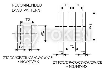 MHz (ZTAC/ZTTC) Recommended Land Pattern
|
|||||||||||||||||||||||||||||||||||||||||||||||||||||||||||||||||||||||||||
Order Codes (ZTAC/ZTTC)
| ZTACC5.00MG | TR | |||||
 | | |||||
|
|
|||||