Ceramic Resonators 190 ~ 1250 KHz (ZTB)
KHz Ceramic Resonators (ZTB) Introduction
Token KHz Ceramic Resonators (ZTB) are Murata resonator CSB compatible.
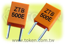
The (ZTB) series ceramic resonators owe their development to Token's expert technologies and the application of mass production techniques typically utilized in the manufacture of piezoelectric ceramic components. Because of their consistent high quality and high mechanical Q, the (ZTB) series are ideally suited to remote control unit and microprocessor applications.
Token Resonators KHz (ZTB) series is designed to provide the engineer with a rugged, relatively low frequency device in the frequency range of 190 kHz to 1,250 kHz. Initial frequency tolerance is ± 0.5 % which compares very favorably to the norminal ± 2% ~ ± 3% requirements of one chip microprocessors. Stability and Aging Tolerance are tight to ± 0.3%.
The (ZTB) series conform to the RoHS directive. Token will also produce devices outside these specifications to meet customer requirements, with comprehensive application engineering and design support available for customers worldwide. Please contact our sales for more information.
Download complete datasheet KHz Ceramic Resonators (ZTB) PDF.
- Oscillating circuits requiring no adjustment can be designed by utilizing these resonators in conjunction with transistors or appropriate ICs.
- The ZTB series is stable over a wide temperature range and with respect to long-term aging.
- Miniature and lightweight, standardized for use in low profile devices.
- Highly reliable design with excellent environmental resistance.
- The ZTB series comprises fixed, tuned, solid-state devices.
- Operation Temperature (-20°C~+80°C).
- Low cost.
- Square-wave and sine-wave oscillators.
- Clock generator for microprocessors.
- Remote control systems.
Dimensions (Unit: mm Tolerance: ±0.3mm) (ZTB)
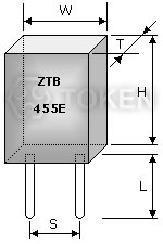 KHz (ZTB) Series Dimensions |
|
Technical Characteristics (ZTB)
| Part Number |
Frequency Accuracy (at 25°C) |
Resonant Impedance (Ω) |
Stability in Temperature (-20°C~+80°C)(%) |
Aging For 10 Years (%) |
Load Capacitance (pF) | |
| C1 | C2 | |||||
| ZTB82 ~ ZTB189 * | ±2kHz | ≤20 | ±0.3 | ±0.3 | / | / |
| ZTB190D ~ ZTB249D | ±1kHz | ≤20 | ±0.3 | ±0.3 | 330 | 470 |
| ZTB250D ~ ZTB374D | ±1kHz | ≤20 | ±0.3 | ±0.3 | 220 | 470 |
| ZTB375P ~ ZTB429P | ±2kHz | ≤20 | ±0.3 | ±0.3 | 120 | 470 |
| ZTB430E ~ ZTB509E | ±2kHz | ≤20 | ±0.3 | ±0.3 | 100 | 100 |
| ZTB510P ~ ZTB699P | ±2kHz | ≤30 | ±0.3 | ±0.3 | 100 | 100 |
| ZTB700J ~ ZTB999J | ±0.5% | ≤70 | ±0.3 | ±0.3 | 100 | 100 |
| ZTB1000J ~ ZTB1250J | ±0.5% | ≤100 | ±0.3 | ±0.3 | 100 | 100 |
* Note : ZTB82 ~ ZTB189 series is new products of custom design.
Resonator Selection - Test Circuit for MOS IC (ZTB)
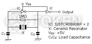
KHz (ZTB) Test Circuit for MOS IC
Loading Capacitor (C1 & C2)
The stability of the oscillation circuit is mainly determined by the C1 & C2 values. If the load capacitance is too small, unstable oscillation will occur because of oscillation waveform distortion. If too high, a stop in oscillation can be expected. When comparing the same IC, oscillation circuits with lower frequencies require higher capacitance. Token Engineers can help with the circuit design if needed.
Feedback Resistor (R = 1MΩ):
A Feedback Resistor is used to determine the oscillation circuit bias. The feedback resistance will contribute to instability if it is too large by reducing feedback. Conversely, if it is too small, increases in current will be realized thereby reducing gain. Recent developments in IC design allows for the integration of the feedback resistor in many cases.
Resonator Optimum - IC Evaluations (ZTB)
Due to the properties of resonators, IC matching must be studied and performed to satisfy oscillation conditions.
Tolerance is determined by the design of the resonator. However stability and correlation is determined by the IC evaluation. The microcontroller is evaluated with the resonators to determine the best possible circuit conditions to achieve stability and stable oscillation.
In addition, frequency correlation is measured to meet the tight initial frequency tolerance required. For the tight tolerance resonators the IC evaluation must be completed on the final circuit board layout. The final circuit boards provide the most accurate measurement of the frequency correlation.
This measurement will account for the effects of stray capacitance on the oscillation frequency. Once the correlation is determined the frequency of the resonator is adjusted to compensate for the correlation.
Order Codes (ZTB)
| ZTB455E | P | |||||||
 | | |||||||
|
|
|||||||