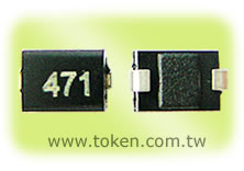
Chip RF Wire Wound Inductors (TREM)
Introduction (TREM322522N, TREM453232N)
Narrow Pad Chip Wire Wound Inductors with High SRFs for RF Applications.
<
>
Token (TREM) Series is primarily designed for chip narrow pad, high SRFs, molded type, wire wound inductors and offers improved performance in the same compact case size. Product conforms to the RoHS directive and Lead-free. The (TREM) series chip RF inductor can be customed designs for tighter tolerances on request.
SMT Inductors TREM322522N and TREM453232N series are revolutionary, high reliable wire wound components for communication, equipment, instruments, video & audio have been developed in response to the trend toward higher density mounting of inductor parts in electric circuits.
Download Complete Specification Chip RF Wire Wound Inductors (TREM) PDF.
Features:
- Metal terminals with excellent connection reliability.
- Accurate dimensions for automatically surface mounted.
- Lead-free materials is used for the plating on the terminals.
- High resistance to heat, humidity, mechanical shocks and presser.
- Good heat durability that withstands lead-free compatible reflow soldering conditions.
Applications :
- (TREM) series is suited for communication, video & audio, equipment, instrument which have been developed
in response to the trend toward higher density mounting of parts in electric circuits.
Operating Temperature:
- Range: -25 ~ +85 °C.
Configurations & Dimensions (Unit: mm) (TREM322522N, TREM453232N)
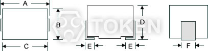
RF Narrow Pad Surface Mount (TREM) Dimensions |
||||||
| Type | A | B | C | D | E | F |
| TREM322522N(1210) | 3.2 ± 0.4 | 2.5 ± 0.2 | 2.9 ± 0.3 | 2.2 ± 0.2 | 0.6 ± 0.2 | 1.0 ± 0.2 |
| TREM453232N(1812) | 4.5 ± 0.4 | 3.2 ± 0.2 | 4.2 ± 0.3 | 3.2 ± 0.2 | 1.0 ± 0.2 | 1.2 ± 0.2 |
Reel & Packaging (TREM322522N, TREM453232N)
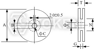
Reel Dimensions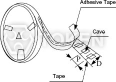
Tape Packing Dimensions |
|||||||
| TYPE | A | B | C | D | G | N | T |
| 8mm | 178 | 21.0±0.8 | 13.0±0.5 | 8 | 10 max | 50 min | 14.4 max |
| 12mm | 178 | 21.0±0.8 | 13.0±0.5 | 10 | 14 max | 50 min | 14.4 max |
Electrical Characteristics (TREM322522N) - EIA 1210
| Part No. | Inductance (µH) |
Tolerance (%) |
Q (min) |
Test Freq. (MHZ) |
SRF (MHz)(min) |
DCR (Ω)(max) |
IDC (mA) |
| TREM322522N - R10* | 0.10 | ±20,±10 | 28 | 100 | 700 | 0.44 | 450 |
| TREM322522N - R12* | 0.12 | ±20,±10 | 30 | 25.2 | 500 | 0.22 | 450 |
| TREM322522N - R15* | 0.15 | ±20,±10 | 30 | 25.2 | 450 | 0.25 | 450 |
| TREM322522N - R18* | 0.18 | ±20,±10 | 30 | 25.2 | 400 | 0.28 | 450 |
| TREM322522N - R22* | 0.22 | ±20,±10 | 30 | 25.2 | 350 | 0.32 | 450 |
| TREM322522N - R27* | 0.27 | ±20,±10 | 30 | 25.2 | 320 | 0.36 | 450 |
| TREM322522N - R33* | 0.33 | ±20,±10 | 30 | 25.2 | 300 | 0.40 | 450 |
| TREM322522N - R39* | 0.39 | ±20,±10 | 30 | 25.2 | 250 | 0.45 | 450 |
| TREM322522N - R47* | 0.47 | ±20,±10 | 30 | 25.2 | 220 | 0.50 | 450 |
| TREM322522N - R56* | 0.56 | ±20,±10 | 30 | 25.2 | 180 | 0.55 | 450 |
| TREM322522N - R68* | 0.68 | ±20,±10 | 30 | 25.2 | 160 | 0.60 | 450 |
| TREM322522N - R82* | 0.82 | ±20,±10 | 30 | 25.2 | 140 | 0.65 | 450 |
| TREM322522N - 1R0* | 1.00 | ±10,±5 | 30 | 7.96 | 120 | 0.70 | 400 |
| TREM322522N - 1R2* | 1.20 | ±10,±5 | 30 | 7.96 | 100 | 0.75 | 390 |
| TREM322522N - 1R5* | 1.50 | ±10,±5 | 30 | 7.96 | 85 | 0.85 | 370 |
| TREM322522N - 1R8* | 1.80 | ±10,±5 | 30 | 7.96 | 80 | 0.90 | 350 |
| TREM322522N - 2R2* | 2.20 | ±10,±5 | 30 | 7.96 | 75 | 1.00 | 320 |
| TREM322522N - 2R7* | 2.70 | ±10,±5 | 30 | 7.96 | 70 | 1.10 | 290 |
| TREM322522N - 3R3* | 3.30 | ±10,±5 | 30 | 7.96 | 60 | 1.20 | 260 |
| TREM322522N - 3R9* | 3.90 | ±10,±5 | 30 | 7.96 | 55 | 1.30 | 250 |
| TREM322522N - 4R7* | 4.70 | ±10,±5 | 30 | 7.96 | 50 | 1.50 | 220 |
| TREM322522N - 5R6* | 5.60 | ±10,±5 | 30 | 7.96 | 45 | 1.60 | 200 |
| TREM322522N - 6R8* | 6.80 | ±10,±5 | 30 | 7.96 | 40 | 1.80 | 180 |
| TREM322522N - 8R2* | 8.20 | ±10,±5 | 30 | 7.96 | 35 | 2.00 | 170 |
| TREM322522N - 100* | 10.0 | ±10,±5 | 30 | 2.52 | 30 | 2.10 | 150 |
| TREM322522N - 120* | 12.0 | ±10,±5 | 30 | 2.52 | 20 | 2.50 | 140 |
| TREM322522N - 150* | 15.0 | ±10,±5 | 30 | 2.52 | 20 | 2.80 | 130 |
| TREM322522N - 180* | 18.0 | ±10,±5 | 30 | 2.52 | 20 | 3.30 | 120 |
| TREM322522N - 220* | 22.0 | ±10,±5 | 30 | 2.52 | 20 | 3.70 | 110 |
| TREM322522N - 270* | 27.0 | ±10,±5 | 30 | 2.52 | 20 | 5.00 | 80 |
| TREM322522N - 330* | 33.0 | ±10,±5 | 30 | 2.52 | 17 | 5.60 | 70 |
| TREM322522N - 390* | 39.0 | ±10,±5 | 30 | 2.52 | 16 | 6.40 | 65 |
| TREM322522N - 470* | 47.0 | ±10,±5 | 30 | 2.52 | 15 | 7.00 | 60 |
| TREM322522N - 560* | 56.0 | ±10,±5 | 30 | 2.52 | 13 | 8.00 | 55 |
| TREM322522N - 680* | 68.0 | ±10,±5 | 30 | 2.52 | 12 | 9.00 | 50 |
| TREM322522N - 820* | 82.0 | ±10,±5 | 30 | 2.52 | 11 | 10.0 | 45 |
| TREM322522N - 101* | 100 | ±10,±5 | 20 | 0.796 | 10 | 10.0 | 40 |
| TREM322522N - 121* | 120 | ±10,±5 | 20 | 0.796 | 10 | 11.0 | 70 |
| TREM322522N - 151* | 150 | ±10,±5 | 20 | 0.796 | 8 | 15.0 | 65 |
| TREM322522N - 181* | 180 | ±10,±5 | 20 | 0.796 | 7 | 17.0 | 60 |
| TREM322522N - 221* | 220 | ±10,±5 | 20 | 0.796 | 7 | 21.0 | 50 |
- Test equipment L, Q: HP4285A +16034E, or equivalent
- SRF: HP8753C NETWORK ANALYZER, or equivalent.
- DC resistance: AX-111A DIGITAL MILLIOHM METER, or equivalent.
Electrical Characteristics (TREM453232N) - EIA 1812 -
| Part No. | Inductance (µH) |
Tolerance (%) |
Q (min) |
Test Freq. (MHZ) |
SRF (MHz)(min) |
DCR (Ω)(max) |
IDC (mA) |
| TREM453232N - R10* | 0.10 | ±10,±20 | 25 | 25.2 | 300 | 0.18 | 800 |
| TREM453232N - R12* | 0.12 | ±10,±20 | 30 | 25.2 | 280 | 0.20 | 770 |
| TREM453232N - R15* | 0.15 | ±10,±20 | 30 | 25.2 | 250 | 0.22 | 730 |
| TREM453232N - R18* | 0.18 | ±10,±20 | 30 | 25.2 | 220 | 0.24 | 700 |
| TREM453232N - R22* | 0.22 | ±10,±20 | 30 | 25.2 | 200 | 0.25 | 665 |
| TREM453232N - R27* | 0.27 | ±10,±20 | 30 | 25.2 | 180 | 0.26 | 635 |
| TREM453232N - R33* | 0.33 | ±10,±20 | 30 | 25.2 | 165 | 0.28 | 605 |
| TREM453232N - R39* | 0.39 | ±10,±20 | 30 | 25.2 | 150 | 0.30 | 575 |
| TREM453232N - R47* | 0.47 | ±10,±20 | 30 | 25.2 | 145 | 0.32 | 545 |
| TREM453232N - R56* | 0.56 | ±10,±20 | 30 | 25.2 | 140 | 0.36 | 520 |
| TREM453232N - R68* | 0.68 | ±10,±20 | 30 | 25.2 | 135 | 0.40 | 500 |
| TREM453232N - R82* | 0.82 | ±10,±20 | 30 | 25.2 | 130 | 0.45 | 475 |
| TREM453232N - 1R0* | 1.00 | ±10,±20 | 40 | 7.96 | 100 | 0.50 | 450 |
| TREM453232N - 1R2* | 1.20 | ±10,±20 | 40 | 7.96 | 80 | 0.55 | 430 |
| TREM453232N - 1R5* | 1.50 | ±10,±20 | 40 | 7.96 | 70 | 0.60 | 410 |
| TREM453232N - 1R8* | 1.80 | ±10,±20 | 40 | 7.96 | 60 | 0.65 | 390 |
| TREM453232N - 2R2* | 2.20 | ±10,±20 | 40 | 7.96 | 55 | 0.70 | 380 |
| TREM453232N - 2R7* | 2.70 | ±10,±20 | 40 | 7.96 | 50 | 0.75 | 370 |
| TREM453232N - 3R3* | 3.30 | ±10,±20 | 40 | 7.96 | 45 | 0.80 | 355 |
| TREM453232N - 3R9* | 3.90 | ±10,±20 | 40 | 7.96 | 40 | 0.90 | 330 |
| TREM453232N - 4R7* | 4.70 | ±10,±20 | 40 | 7.96 | 35 | 1.00 | 315 |
| TREM453232N - 5R6* | 5.60 | ±10,±20 | 40 | 7.96 | 33 | 1.10 | 300 |
| TREM453232N - 6R8* | 6.80 | ±10,±20 | 40 | 7.96 | 27 | 1.20 | 285 |
| TREM453232N - 8R2* | 8.20 | ±5,±10 | 40 | 7.96 | 25 | 1.40 | 270 |
| TREM453232N - 100* | 10.0 | ±5,±10 | 40 | 2.52 | 20 | 1.60 | 250 |
| TREM453232N - 120* | 12.0 | ±5,±10 | 40 | 2.52 | 18 | 2.00 | 225 |
| TREM453232N - 150* | 15.0 | ±5,±10 | 40 | 2.52 | 17 | 2.50 | 200 |
| TREM453232N - 180* | 18.0 | ±5,±10 | 40 | 2.52 | 15 | 2.80 | 190 |
| TREM453232N - 220* | 22.0 | ±5,±10 | 40 | 2.52 | 13 | 3.20 | 180 |
| TREM453232N - 270* | 27.0 | ±5,±10 | 40 | 2.52 | 12 | 3.60 | 170 |
| TREM453232N - 330* | 33.0 | ±5,±10 | 40 | 2.52 | 11 | 4.00 | 160 |
| TREM453232N - 390* | 39.0 | ±5,±10 | 40 | 2.52 | 10 | 4.50 | 150 |
| TREM453232N - 470* | 47.0 | ±5,±10 | 40 | 2.52 | 10 | 5.00 | 140 |
| TREM453232N - 560* | 56.0 | ±5,±10 | 40 | 2.52 | 9 | 5.50 | 135 |
| TREM453232N - 680* | 68.0 | ±5,±10 | 40 | 2.52 | 9 | 6.00 | 130 |
| TREM453232N - 820* | 82.0 | ±5,±10 | 40 | 2.52 | 8 | 7.00 | 120 |
| TREM453232N - 101* | 100 | ±5,±10 | 30 | 0.796 | 8 | 8.00 | 110 |
| TREM453232N - 121* | 120 | ±5,±10 | 30 | 0.796 | 6 | 8.00 | 110 |
| TREM453232N - 151* | 150 | ±5,±10 | 30 | 0.796 | 5 | 9.00 | 105 |
| TREM453232N - 181* | 180 | ±5,±10 | 30 | 0.796 | 5 | 9.50 | 102 |
| TREM453232N - 221* | 220 | ±5,±10 | 30 | 0.796 | 4 | 10.0 | 100 |
| TREM453232N - 271* | 270 | ±5,±10 | 30 | 0.796 | 4 | 12.0 | 92 |
| TREM453232N - 331* | 330 | ±5,±10 | 30 | 0.796 | 3.5 | 14.0 | 85 |
| TREM453232N - 391* | 390 | ±5,±10 | 30 | 0.796 | 3 | 18.0 | 80 |
| TREM453232N - 471* | 470 | ±5,±10 | 30 | 0.796 | 3 | 26.0 | 62 |
| TREM453232N - 561* | 560 | ±5,±10 | 20 | 0.796 | 3 | 30.0 | 50 |
| TREM453232N - 681* | 680 | ±5,±10 | 20 | 0.796 | 3 | 30.0 | 50 |
| TREM453232N - 821* | 820 | ±5,±10 | 20 | 0.796 | 2.5 | 35.0 | 30 |
| TREM453232N - 102* | 1000 | ±5,±10 | 10 | 0.252 | 2.5 | 40.0 | 30 |
- Test equipment L, Q: HP4285A +16034E, or equivalent
- SRF: HP8753C NETWORK ANALYZER, or equivalent.
- DC resistance: AX-111A DIGITAL MILLIOHM METER, or equivalent.
Mechanical Performance Test (TREM322522N, TREM453232N)
| REQUIREMENTS | CHARACTERISTICS | TEST METHOD(DIS C 5321) |
| Terminal Strength | No evidence of damage | Terminals shall withstand a pull of 0.5Kgf in a horizontal direction |
| Vibration | Δ L/L shall be within ±3%. No evidence of damage |
2 hours in each direction of X,Y,Z on p-Board at a frequency range of 10-55-10HZ with 1.5mm amplitude |
| Dropping | Δ L/L shall be within ±3%. No evidence of damage |
Dropping 1m over the ground of concrete or cement |
TREM322522N, TREM453232N Series RF Chip Wirewound Inductors - Electrical Performance Test
| REQUIREMENTS | CHARACTERISTICS | TEST METHOD(JIS C 5321) |
| Resistance to Soldering Heat |
No evidence of damage Δ L/L shall be within ±3% |
Immerse in the solder (H63A)of 260±5°C for 10±1sec, leave for 2hrs at normal TEMP |
| Solderability | More than 90% surface to be covered with new soldering |
AV100V 60 SEC. |
| Dielectric with withstanding voltage |
No evidence of breakdown resistor 1000 Mohm and over |
DC500V 30 SEC. |
| Insulation Resistance | No veidence of breakdown, resistor 1000 Mohm and over |
DC 500V 30 SEC. |
Climatic Test (TREM322522N, TREM453232N)
| REQUIREMENTS | CHARACTERISTICS | TEST METHOD(JIS C 5321) |
| LOW TEMP. Characteristics |
No evidence of damage, Δ L/L within ±5%, Q/Q within ±30% |
Immerse in the solder (H63A)of 260±5°C for 10±1sec, leave for 2hrs at normal TEMP. |
| TEMP. Cycling | No evidence of damage, Δ L/L within ±5% |
Keep for 30 min. at TEMP.of -25°C~+85°C at 5 cycle case of TEMP. change from low to high and V.V. |
| Temperature Characteristics |
Δ L/L within ±3% | Δ L/L to be measured at the temperature of between -25°C and +85°C |
| Moiisture load Characteristics |
No evidence of damage, Δ L/L within ±5%, Q/Q within ±30 |
TEMP.40±2°C,Humidity 90~95% 96± 2hrs, measurements shall be performed after 1~2hrs at normal TEMP.. |
| High TEMP. overload Characteristics |
No evidence of damage, Δ L/L within ±5%, Q/Q within ±30 |
Leave for 96±2hrs in a bath of TEMP.85±2°C, measurements shall be performed after 1~2hrs at normal TEMP. |
Order Codes (TREM322522N, TREM453232N)
| TCEC322522N | - | 1R0 | M | |||||||||||||||||||||||||
 |
|
|
||||||||||||||||||||||||||
|
|
|
||||||||||||||||||||||||||