RFID Transponder Coils (TR4308I)
Introduction (TR4308I)
Transponder Coils (TR4308I) is The Key of Radio Frequency Identification (RFID) System.
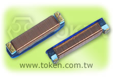
Token (TR4308I) RFID coil series is specified for RFID applications for the best performing designed at 125 kHz. The (TR4308I) covers a wide range of electrical performances and offers better sensitivity, greater read distance and higher SRF than other coils its size.
The TR4308I's length and cross section area are optimized for best sensitivity in the coil axis. The coil is wound on a plastic base, providing great durability and allowing this part to withstand harsh mechanical shock. With operating temperature range to 125°C, these coils are ideal for a wide range of applications.
Radio Frequency Identification (RFID) is the system of using radio signals to send information identifying a particular situation or item. Token (TR4308I) is suited for wireless data transmission in low frequency RFID products, such as immobilizers, TPMS, keyless entry. Other industrial applications include access control and tracking devices.
In addition to our standard models, Token can design RFID coils to operate at other frequencies. Customized inductance values are available on request.
Download complete specification (TR4308I) PDF.
- High Q value.
- Low profile with an extended length.
- Car remote control key.
RFID Transponder Configurations & Dimensions (Unit: mm) (TR4308I)
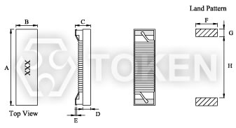
SMD RFID Transponder Coils (TR4308I) Dimensions |
||||||||
| Type | A | B | C | D | E | F | G | H |
| TR4308I | 11.43 | 3.15 | 2.74 | 1.01 | 0.51 | 2.79 | 1.78 | 8.46 |
- Note: Design as Customer's Requested Specifications.
Electrical Characteristics (TR4308I)
| Part Number | Inductance (mH) |
Q (min) |
Test Freq. (KHz) |
SRF (KHz)(min) |
DCR (Ω)(max) |
| TR4308I - 401J | 0.40 | 15 | 125 | 4500 | 7.4 |
| TR4308I - 901J | 0.90 | 15 | 125 | 4000 | 22 |
| TR4308I - 112J | 1.08 | 15 | 125 | 4000 | 25 |
| TR4308I - 202J | 1.97 | 17 | 125 | 2400 | 34 |
| TR4308I - 242J | 2.38 | 17 | 125 | 2200 | 39 |
| TR4308I - 332J | 3.30 | 17 | 125 | 1800 | 51 |
| TR4308I - 412J | 4.15 | 17 | 125 | 1700 | 74 |
| TR4308I - 492J | 4.90 | 17 | 125 | 1300 | 96 |
| TR4308I - 682J | 6.80 | 17 | 125 | 1000 | 112 |
| TR4308I - 712J | 7.10 | 17 | 125 | 1000 | 115 |
| TR4308I - 812J | 8.10 | 17 | 125 | 960 | 123 |
- Note: Test Freq.: 125KHz / 0.25V. Operating Temp.: -40°C+85°C.
RFID, Radio Frequency Identification System and Applications
Figure 1. RFID System
RFID, Radio Frequency Identification, is the system of using radio signals to send information identifying a particular item. The most common application of RFID is to track and locate any subject including material, or moving item.
The RFID coil is part of the coupling device and acts as the transmitting antenna. The main specifications of the RFID coils are sensitivity and read distance, however, the inductance of the RFID coil directly influences the sensitivity and the read distance. Generally, a higher inductance provides greater sensitivity resulting in a longer read distance.
The manufacturer of the tag usually specifies the inductance of the coil to be used. The read distance is defined as the maximum distance from the reader that the transponder responds to the reader's magnetic field. The reader produces a magnetic field that triggers the tag. When the reader receives the transmitted data, it interprets the data and takes appropriate action as shown in figure 1.
When the transponder enters the field produced by the reader, the coil produces a voltage inside the tag. In an active transponder, the voltage is used to wake the tag and use its internal battery. In a passive transponder, this voltage can be used to power the tag. Active transponders generally have longer read distances, shorter operational life and are larger and more costly to manufacture. Passive transponders are generally smaller, have a longer life and are less expensive to manufacture.
There are two major components in an RFID system:
- Tag:
The transponder programmed with unique information.
The tag consists of an integrated circuit and a coupling device. The integrated circuit stores specific data unique to that tag. - Reader:
The interrogator includes a decoder to interpret data. The coupling device interfaces with the reader.
Figure 2. LC Circuit
For optimum performance, the RFID coil is used in a parallel LC circuit as shown in figure 2. Adding a capacitor to the circuit maximizes the read distance. The LC circuit is designed to resonate at the operating frequency of the reader. To calculate
the value of the capacitor, use the following
Equation: Capacitance (C) = 1 / (Inductance L x (2π x Frequency ƒ))2
Order Codes (TR4308I)
| TR4308I | - | 401 | J | ||||||||||||||
 |
|
|
|||||||||||||||
|
|
|
|||||||||||||||