Custom Saw Design and Manufacturing
Saw Filters
For marketing discontinuations or second sourcing activities concerning RF Filter and IF Filter products, you are encouraged to contact our Sales Department so the request can be properly directed within Token.
Saw Resonators
For marketing discontinuations or second sourcing activities concerning RF Filter and IF Filter products, you are encouraged to contact our Sales Department so the request can be properly directed within Token.
Saw Applications for Telecommunications
Definition of Saw

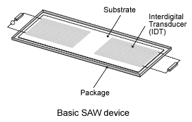
Figure-1 - Basic Saw Device
Surface Acoustic Wave (SAW) is a wave propagating along the surface of an elastic substrate. Frequency of Saw is:
F = V / λ
Where V is the velocity of SAW (~3,100m/s), λ is the IDT period.
Types of Saw Devices
The device in (Figure-1) is a basic delay line, because the wave takes some time to travel between the transducers - typically 1 μs for 3 mm of path length. This is very compact compared with EM waves which, in free space, need 300 m of path for 1 μs delay. The device can also be used as a bandpass filter, because the transducers operate most effectively when the saw wavelength equals the transducer pitch - at other frequencies the waves generated by individual gaps are not in phase, so the wave amplitude falls off as the frequency is changed.
Another basic device is the resonator. This uses arrays of metal strips, with pitch λ/2, as reflectors of the waves. These arrays can give strong Saw reflections, and two arrays can be used to form a saw cavity with high Q, up to 105. Such resonators are often used for high-stability oscillators.
The above devices are just some basic types. Many unique variations are possible for saw devices, and their applications range from piezoelectric strain gauges to pulse compression radar, to cellular handsets.
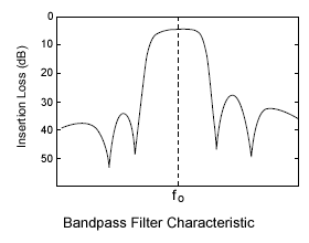
The most common group are bandpass filters, which are in very widespread use in radio systems (including mobile phone handsets and base stations) and in domestic TV. There are many types with differing advantages, such as low shape factor, low insertion loss, small size, or high-frequency operation. The wide variety of types is possible because almost arbitrary shapes can be defined on the surface with very high precision, using lithography techniques similar to those for semiconductor processing. A typical saw Bandpass characteristic is shown if (Figure-2).
Saw Applications

Figure-2 - Bandpass Filter Characteristic
Surface acoustic wave filters play a key role in telecommunications. Because of their special features various products are being used more and more in different transmission systems:
- Passband filter typically as RF or IF filters for data processing in communication systems. A few examples for these applications are mobile phone basestations, point to multipoint systems, radio link systems, Professional Mobile Radio (PMR) systems and Wireless Local Loop (WLL) systems.
- Clock recovery filters for digital regeneration in fiber-optic systems, e.g. FDDI, ISDN, LAN, etc.
- Nyquist and Vestigial sideband filters in television transmission systems in TV transmitters and high quality receivers, modulators/demodulators, and converters of CATV head-ends, etc.
- Passband filters for basestations include filters for all worldwide standards (TDMA, CDMA, GSM, and W-CDMA). Filters for WLL systems are available for products based on CDMA, W-CDMA, DECT, GSM, and proprietary standards. Trunked radio filters for PMR basestation, mobile and handheld applications are offered for the digital standard TETRA.
PDF Catalogue
Download Saw Applications for Telecommunications in PDF file.
General Information of Saw
Advantage of Token Saw Devices
Token Electronics has gained a successful development of Saw components, due to our flexible design capabilities and cost-optimizing production facilities.
In addition to our extensive offering of standard Saw devices, Token has diverse Engineering experience spanning hundreds of custom designed saw components, Bandpass Filters, Low Loss Filters and saw based subsystems.
As Token Company Spirit:
- Honesty is our business policy.
- Perfection is our quality system.
- Sharing cost saving with customers is our business target.
Token reliably deliver high-quality components according to the each customer special needs with respect to performance, costs, and technology modifications.
Download Complete Token SAW Product Catalogue in PDF file .
Required to effectively design a Saw Component

Filter Group Delay Variation over Pass Bandwidth
Generally, a saw manufacturer will offer their most popular devices as standards creating a reference for Engineers to design from. Typically, a standard device is available for most common applications.
However, for applications requiring parameters that are not currently considered industry standards. In this case, the following information is required to effectively design a filter:
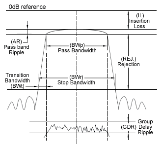
Insertion Loss (IL)
The logarithmic ratio of the power delivered to the load impedance before the filter is inserted to the power delivered to the load impedance after the filter is inserted. Unit of Insertion loss in is dB.
Advances in filter design techniques routinely allow for a design incorporating a specification of under 10dB Insertion Loss, however, the minimum attainable Insertion Loss is generally influenced by the Fractional Bandwidth and the influences of this ratio on the applicable substrate material.
The Insertion Loss value will generally increase when approaching the fractional bandwidth limit of a substrate material. For instance, a Fractional Bandwidth value of 8% will generally produce lower Insertion Loss than a Fractional Bandwidth value of 30% using the same substrate material.
Pass Bandwidth (BWp)
The frequency interval in which the relative attenuation (the attenuation from the minimum insertion loss) is equal to the specified value 3dB.
Nominal Frequency (Fn)
The nominal values of the center frequency F0 and is used as the reference frequency of related standard. Unit of nominal frequency is in MHz.
Stop Bandwidth (BWr)
The frequency interval in which the relative attenuation (the attenuation from the minimum insertion loss) is equal to the specified value of "A" dB.
Transition Bandwidth (BWt)
Otherwise referred to as Skirts, the area between the Stop Band and the Passband found on both sides of the Passband.
Pass band Ripple (AR)
The difference between the minimum peak attenuation and the maximum peak attenuation within a pass band. Unit is in dB.
Group Delay Ripple (GDR)
The difference between the maximum and minimum value of the group delay in the specified range of the pass band. Unit in μs.
Rejection (REJ.)
All ranges of the saw components not including the Passband. The Rejection can also be referred to as the Rejection Range, or Stop Band. We can refer to this as the range in which the Relative Attenuation is larger than the specified Rejection side.
With proper material selection and design, Rejection of 50dB, or greater, is possible within a wide selection of fractional bandwidths and shape factors.
Terminating Impedance (Zt)
Impedance presented to the filter by the source or by the load.
Package
Factors affecting the size of the package used in saw design include parameters associated with Center Frequency, Bandwidth, and Shape Factor, among other minor considerations.
For instance, lower Frequencies require larger substrate, thereby increasing the size of the packages available to the designer. Consequently, an equally important challenge of package size reduction is always considered by Token Design Engineers in an attempt to meet the desired parameters in the smallest package possible.
In selecting a package, we recommend stating general preferences. Without this input, Token will design using the most cost effective approach balancing parameter requirements with cost and manufacturability.
PDF Catalogue
Download General Info. of Saw Devices in PDF file.
Correlation
Saw Package Dimensions
SMD and DIP Type Package Dimensions of Saw components.
Download Complete Saw Package Dimension Specification of Filters and Resonators - PDF
Build a Custom Saw Components
What is a Saw? Saw device characteristics, fundamentals, manufacturing process, paramenters, etc..
Download How to Build a Custom Saw Devices - PDF

