Build a Custom Saw Components
Definition of SAW
Surface Acoustic Wave (SAW) is a wave propagating along the surface of an elastic substrate. Frequency of SAW is:
F = V / λ
Where V is the velocity of Saw (~3,100m/s), λ is the IDT period.
What is a Saw Filter
Figure-1 - Basic Saw Device
A surface acoustic wave (SAW) is a type of mechanical wave motion which travels along the surface of a solid material. The wave was discovered in 1885 by Lord Rayleigh, and is often named after him. Rayleigh showed that SAWs could explain one component of the seismic signal due to an earthquake, a phenomenon not previously understood. These days, these acoustic waves are often used in electronic devices. At first sight it seems odd to use an acoustic wave for an electronic application, but acoustic waves have some particular properties that make them very attractive for specialized purposes. And they are not unfamiliar-many wristwatches have a quartz crystal used for accurate frequency generation, and this is an acoustic resonator though it uses bulk acoustic waves rather than surface waves.
A basic saw device (Figure-1) consists of two interdigital transducers (IDTs) on a piezoelectric substrate such as quartz. The IDTs consist of interleaved metal electrodes which are used to launch and receive the waves, so that an electrical signal is converted to an acoustic wave and then back to an electrical signal. A basic advantage is that acoustic waves travel very slowly (typically 3000 m/s), so that large delays are obtainable. The IDT geometry is capable of almost endless variation, leading to a wide variety of devices. Starting around 1970, saw devices were developed for pulse compression radar, oscillators, and bandpass filters for domestic TV and professional radio. In the 1980s the rise of mobile radio, particularly for cellular telephones, caused a dramatic increase in demand for filters. New high-performance saw filters emerged and vast numbers are now produced, around 3 billion annually.
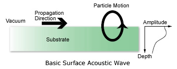
Figure-2 - Basic Surface Acoustic Wave
(Figure-2) shows a saw travelling along the plane surface of a solid material. As the wave passes, each atom of the material traces out an elliptical path, repeating the path for each cycle of the wave motion. The atoms move by smaller amounts as one looks farther into the depth, away from the surface. Thus, the wave is guided along the surface. In the simplest case (an isotropic material), the atoms move in the so-called sagittal plane, i.e. the plane which includes the surface normal and the propagation direction.
Piezoelectricity for SAW
For electronic devices, we need to generate the SAWs from an electrical input signal, and then use the Saw to generate an electrical output signal. The conversion process (electric to acoustic, or acoustic to electric) is called 'transduction.' To explain this, we first have to consider piezoelectricity, which is a property of many solid materials. In a piezoelectric material there is a mechanism which offers coupling between electrical and mechanical disturbances. Hence, application of an electric field sets up mechanical stresses and strains. Conversely, a mechanical stress due to pressure, for example, gives an electric field, and hence a voltage.
Figure-3 - Quartz Orientations
Piezoelectricity occurs in many materials but there is a primary requirement that the material must be anisotropic, so that its properties depend on the orientation relative to the internal arrangement of the atoms. Usually, this means that crystalline materials must be used. The commonest materials for SAWs are crystals of quartz, lithium niobate or lithium tantalate, which are all piezoelectric. In these crystals the saw motion is similar to that of the isotropic case described earlier, though with the difference that the wave now has an electric field associated with it. Another important factor is because the material is anisotropic, the saw properties depend on the orientation at which the substrate has been cut from the original material, so this must be specified. Examples of cuts are shown in (Figure-3).
Saw designers normally use 'standard' orientations known to give good saw properties. An example is 34° Y-X quartz, meaning that the saw propagates in the crystal X-direction, on a plate with the surface normal rotated 34° from the Y-axis. Rotated Y cuts of quartz in this region give parabolic frequency temperature characteristics, and hence provide excellent temperature stability. The turnover temperature may be varied by adjusting the cut angle. Many of these rotated Y cuts are given special names such as ST for 42.75°, CT for 38°, AT for 35.25°. As for isotropic materials, the waves are nondispersive (velocity independent of frequency), and the attenuation can be very low.
Piezoelectricity is a great help for transduction. If an electric field is applied to the surface, corresponding stresses are set up which travel away from the source in the form of SAWs. The easiest method is to use a set of interleaved electrodes alternately connected to two bus bars, as in (Figure-1). The left transducer is launching the waves. When a voltage is applied, the gaps between electrodes have electric fields and, via the piezoelectric effect, mechanical stresses.
The fields and stresses alternate in sign because of the alternating connections of the electrodes,and the stresses act as sources of surface waves. If the frequency is chosen such that the saw wavelength equals the transducer pitch, the waves generated by subsequent gaps are all in phase and therefore reinforce each other. For a given voltage, a longer transducer will give a larger wave amplitude. The transducer on the right is the same structure but used to receive the waves, i.e. to give an output voltage in response to an incident wave. It operates in a reciprocal manner to the launching transducer, so a longer transducer will give a larger voltage for a given saw amplitude.
Saw Filters Characteristics
- Saw filter is an integrated, passive device with bandpass filter characteristics.
- Operation is based on the interference of mechanical surface waves.
- Input/Output transducers are formed on a piezoelectric material.
Saw Filters Advantages
- Reduced size and weight.
- High reliability and ruggedness.
- No tuning or readjustment.
- Mass production capable.
Saw Filters Fundamentals
A SAW device works by "acoustic" propagation
through a ceramic medium.
Saw devices consist of two transducers with interdigital transducers of thin metal electrodes deposited on a piezoelectric substrate such as quartz or lithium tantalite. One of these acts as the device input and converts signal voltage variations into mechanical surface acoustic waves. The other IDT is used as an output receiver to convert mechanical saw vibrations back into output voltages. Such energy conversions require the Interdigital transducers to be used in conjunction with elastic surfaces that are also piezoelectric ones.
Saw Filters Manufacturing Process
- Wafer (LiTaO3 or LiNbO3, or SiO2)
- Al deposit (sputtering) 0.15μ to 1.5μ
- Photoresist (PR coating)
- Exposure
- Develop
- Al etching (Wet etching)
- PR removal
- QC check + Probing (F0, IL)
- Sieving (Scribing)
- QC check (chips, cracks)
- Mounting Ag/UV bond
- Wire bonding
- Seam sealing
- Marking
- Final tests and inspections
Saw Filter Parameters
- Nominal frequency Fn (MHz)
- Pass Bandwidth 3dB BWp (MHz)
- Stop Bandwidth BWr (MHz)
- Insertion Loss IL (dB)
- Pass Band Ripple AR (dB)
- Group Delay GD (μs)
- Temperature coefficient TC (ppm/°C)
- Termination Impedance (ohms)
- Operating temperature range T (°C)
Handling Precautions
- Use the saw product within its maximum ratings.
- Never apply voltage higher than the maximum rating since h i gh level voltage could accelerate deterioration of the saw characteristics.
- The shield grounding condition should be determined so that electrical coupling between input and output may be minimized before using the device. Coupling between input and output will cause ripples in the pass band amplitude and group delay.
- Storage temperature shall not exceed 85°C.
- Be careful when using ultrasonic cleaning saw products since device material and construction is sensitive to ultrasonic vibration.
- Do not apply sudden or excessive thermal or mechanical shock to the saw products since it could worsen or deteriorate the saw characteristics.
Environmental and Mechanical Specifications
- Shock (Drop test)
Natural drop on a hardwood board at 1.0m, 3 times. The specimens shall meet the electrical specifications.
- Vibration
Frequency with an amplitude of 1.5mm sweeping between 10Hz to 55Hz within 1 minute for 2 hours minimum on each axis on three (3) mutually perpendicular axes. The specimens shall meet the electrical specifications.
- Resistance to solder heat
Immerse the leads or terminals in soldering bath at 245° ±5°C for 5 ±0.5 s. 75% or more of the immersed surface shall be covered with solder.
- Temperature characteristics
Specimens shall be measured within -40°C to +85°C temperature range. The specimens shall meet the electrical specifications.
- Dry heat (aging test)
Temperature 125°C ±2°C for 250 hours. The specimens shall meet the electrical specifications.
- Cold resistance
Temperature - 40°C ±3°C. Duration 96 hours. The specimens shall meet the electrical specifications.
- Thermal shock
Heat cycle conditions -55°C (30 minutes), 25°C (5 minutes), +85°C (30 minutes) for 5 cycles. The specimens shall meet the electrical specifications.