Large Current Inductors (TPSRH-74B/125B/127B) Shielded
Introduction (TPSRH-74B/125B/127B)
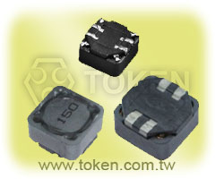
Token (TPSRH) shielded large current inductor family series is a strong choice for Power saving.
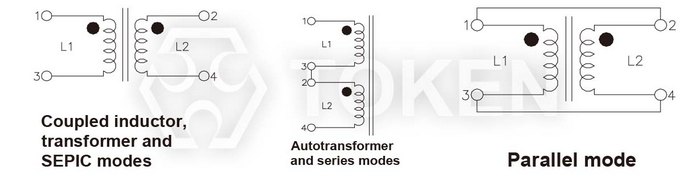
Token four pin terminals flexible design Surface Mount Wirewound Inductor constructs with four terminal pin type which gives a flexible design as inductors or transformers (SEPIC, ZETA circuit, etc).
Provide wide inductance range from 2.5μH to 1000.0μH in parallel connection, low direct current resistance (DCR) down to 0.018Ω, and large current up to 14.9A. These devices are directly connected electrode on ferrite core with excellent property and high saturation for surface mounting.
Token enhances surface mount inductor (TPSRH) family series covering complete footprint with profile from 4.8 mm to 8.5 mm, inductance from 1.00 μH to 1000.00 μH, low DCR, and Rated Current uo to 10.0A.
Token (TPSRH74B/125B/127B) with wire wound and magnetically shielded construction offers a variety of characteristics and high performace. Customers can select the optimum characteristics by choosing from footprint, DCR, and a wide range of inductance values and tolerances with some types offering magnetic shielding.
The series is lead-free and RoHS compliant. Application of specific designs also available including different inductance and frequency specifications adjusted to requirements. Please contact our sales for more information.
Download Complete Datasheet Large Current Inductors (TPSRH) PDF.
- Power saving for low voltage power supply
- Four terminals choke coil available for DC-DC Converter of less than 3.3V input voitage.
- P.D.A., Notebook size personal computer, MPU driving power supply, Logic IC Power supply.
Dimensions & Configurations (Unit: mm) (TPSRH-74B/125B/127B)
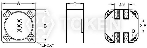 SMT Power Backlight Inductors (TPSRH74B) Dimensions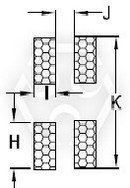 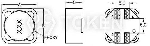 SMT Power Backlight Inductors (TPSRH125B/TPSRH127B) Dimensions |
|||||||
 SMT Power Backlight Inductors (TPSRH74B) Dimensions |
|||||||
| Type | A Max. | B Max. | C Max. | I | J | H | K |
| TPSRH74B | 7.3±0.3 | 7.3±0.3 | 4.8 | 1.1 | 0.8 | 2.1 | 7.5 |
| TPSRH125B | 12.0±0.3 | 12.0±0.3 | 6.5 | 2.0 | 1.5 | 4.0 | 12.5 |
| TPSRH127B | 12.0±0.3 | 12.0±0.3 | 8.5 | 2.0 | 1.5 | 4.0 | 12.5 |
Note: Design as Customer's Requested Specifications.
Winding Schematics (TPSRH74B)
| PART NO | Ieads connected in parallel | Ieads connected in series | ||||||||
| L (µH) |
DCR (OHM) Max. |
Isat (A) 30%drop typ |
SRF MHz |
Irms (A) |
L (µH) |
DCR (OHM) Max. |
Isat (A) 30%drop typ |
SRF MHz |
Irms (A) |
|
| TPSRH74B-2R5 | 2.5 | 0.018 | 6.30 | 55.0 | 4.33 | 10.0 | 0.072 | 3.15 | 17.60 | 2.17 |
| TPSRH74B-3R3 | 3.3 | 0.022 | 5.40 | 43.0 | 4.09 | 13.2 | 0.088 | 2.70 | 12.90 | 2.05 |
| TPSRH74B-4R7 | 4.7 | 0.026 | 4.60 | 35.0 | 3.48 | 18.8 | 0.102 | 2.30 | 9.80 | 1.74 |
| TPSRH74B-5R6 | 5.6 | 0.032 | 4.20 | 32.0 | 3.14 | 22.4 | 0.126 | 2.10 | 8.48 | 1.57 |
| TPSRH74B-6R8 | 6.8 | 0.035 | 3.90 | 30.0 | 2.97 | 27.2 | 0.140 | 1.95 | 7.92 | 1.49 |
| TPSRH74B-8R2 | 8.2 | 0.043 | 3.50 | 27.0 | 2.87 | 32.8 | 0.172 | 1.75 | 7.10 | 1.44 |
| TPSRH74B-100 | 10 | 0.050 | 3.00 | 22.0 | 2.49 | 40 | 0.20 | 1.50 | 5.75 | 1.24 |
| TPSRH74B-120 | 12 | 0.060 | 2.70 | 20.0 | 2.28 | 48 | 0.24 | 1.35 | 5.18 | 1.14 |
| TPSRH74B-150 | 15 | 0.070 | 2.40 | 18.0 | 2.18 | 60 | 0.28 | 1.20 | 4.59 | 1.09 |
| TPSRH74B-180 | 18 | 0.085 | 2.30 | 15.0 | 1.91 | 72 | 0.34 | 1.15 | 3.80 | 0.95 |
| TPSRH74B-220 | 22 | 0.110 | 2.10 | 13.5 | 1.68 | 88 | 0.44 | 1.05 | 3.38 | 0.84 |
| TPSRH74B-270 | 27 | 0.125 | 1.90 | 12.0 | 1.57 | 108 | 0.50 | 0.95 | 2.98 | 0.79 |
| TPSRH74B-330 | 33 | 0.150 | 1.70 | 11.0 | 1.51 | 132 | 0.60 | 0.85 | 2.68 | 0.76 |
| TPSRH74B-390 | 39 | 0.190 | 1.50 | 10.0 | 1.27 | 156 | 0.76 | 0.75 | 2.40 | 0.64 |
| TPSRH74B-470 | 47 | 0.21 | 1.40 | 9.50 | 1.22 | 188 | 0.84 | 0.70 | 2.23 | 0.61 |
| TPSRH74B-560 | 56 | 0.27 | 1.30 | 8.70 | 1.16 | 224 | 1.08 | 0.65 | 2.16 | 0.58 |
| TPSRH74B-680 | 68 | 0.32 | 1.20 | 7.30 | 1.02 | 272 | 1.28 | 0.60 | 1.73 | 0.51 |
| TPSRH74B-820 | 82 | 0.36 | 1.10 | 6.20 | 0.95 | 328 | 1.44 | 0.55 | 1.35 | 0.49 |
| TPSRH74B-101 | 100 | 0.45 | 0.98 | 5.50 | 0.89 | 400 | 1.80 | 0.49 | 1.18 | 0.45 |
| TPSRH74B-121 | 120 | 0.56 | 0.90 | 4.50 | 0.78 | 480 | 2.24 | 0.45 | 1.10 | 0.39 |
| TPSRH74B-151 | 150 | 0.675 | 0.80 | 4.00 | 0.68 | 600 | 2.70 | 0.40 | 0.82 | 0.34 |
| TPSRH74B-181 | 180 | 0.83 | 0.73 | 3.80 | 0.61 | 720 | 3.32 | 0.36 | 0.72 | 0.32 |
| TPSRH74B-221 | 220 | 1.10 | 0.66 | 3.50 | 0.59 | 880 | 4.40 | 0.33 | 0.63 | 0.30 |
| TPSRH74B-271 | 270 | 1.30 | 0.60 | 3.30 | 0.51 | 1080 | 5.20 | 0.30 | 0.58 | 0.25 |
| TPSRH74B-331 | 330 | 1.60 | 0.54 | 3.00 | 0.48 | 1320 | 6.40 | 0.27 | 0.53 | 0.24 |
| TPSRH74B-391 | 390 | 2.10 | 0.50 | 2.80 | 0.45 | 1560 | 8.40 | 0.25 | 0.48 | 0.23 |
| TPSRH74B-471 | 470 | 2.35 | 0.46 | 2.60 | 0.40 | 1880 | 9.40 | 0.23 | 0.42 | 0.20 |
| TPSRH74B-561 | 560 | 2.65 | 0.42 | 2.50 | 0.37 | 2240 | 10.6 | 0.21 | 0.39 | 0.19 |
| TPSRH74B-681 | 680 | 3.50 | 0.38 | 2.30 | 0.35 | 2720 | 14.0 | 0.19 | 0.34 | 0.18 |
| TPSRH74B-821 | 820 | 3.90 | 0.35 | 2.20 | 0.30 | 3280 | 15.6 | 0.175 | 0.32 | 0.15 |
| TPSRH74B-102 | 1000 | 5.40 | 0.31 | 2.00 | 0.28 | 4000 | 21.6 | 0.155 | 0.28 | 0.144 |
- DCR is for both windings . DC current at which the inductance drops 30% (typ) from its value without current.
- Inductance tolerance: 4.7μH~100μH tolerance can be done “M” 120μH~1000μH tolerance can be done “K”.
Note:
- Inductance shown for coupled inductor and for two inductors connected in parallel .
- Inductance is measured at 100KHz.0.1Vrms.0Adc on an Agilent/HP 4284ALC meter or equivalent .
- DCR is for both windings when connected in parallel.DCR for each winding is twice the Value .
- SRF measured using Agilent/HP E4991A or equivalent .
- Current that causes a 40°C temperature rise from 25°C ambient .
Winding Schematics (TPSRH125B)
| PART NO | Ieads connected in parallel | Ieads connected in series | ||||||||
| L (µH) |
DCR (OHM) Max. |
Isat (A) 30%drop typ |
SRF MHz |
Irms (A) |
L (µH) |
DCR (OHM) Max. |
Isat (A) 30%drop typ |
SRF MHz |
Irms (A) |
|
| TPSRH125B-4R7 | 4.7 | 0.018 | 10.30 | 32.0 | 7.2 | 18.8 | 0.072 | 5.15 | 12.00 | 3.4 |
| TPSRH125B-5R6 | 5.6 | 0.020 | 9.66 | 31.0 | 7.0 | 22.4 | 0.080 | 4.83 | 10.30 | 3.3 |
| TPSRH125B-6R8 | 6.8 | 0.024 | 9.21 | 28.0 | 6.6 | 27.2 | 0.095 | 4.61 | 8.40 | 3.2 |
| TPSRH125B-8R2 | 8.2 | 0.026 | 8.55 | 25.0 | 6.4 | 32.8 | 0.104 | 4.28 | 7.10 | 3.1 |
| TPSRH125B-100 | 10 | 0.030 | 7.40 | 22.0 | 5.40 | 40.0 | 0.120 | 3.70 | 6.00 | 2.8 |
| TPSRH125B-120 | 12 | 0.037 | 6.86 | 21.0 | 5.2 | 48.0 | 0.147 | 3.43 | 5.80 | 2.7 |
| TPSRH125B-150 | 15 | 0.042 | 6.09 | 17.6 | 4.6 | 60 | 0.170 | 3.05 | 5.50 | 2.5 |
| TPSRH125B-180 | 18 | 0.048 | 5.30 | 17.0 | 4.4 | 72 | 0.194 | 2.65 | 5.00 | 2.2 |
| TPSRH125B-220 | 22 | 0.058 | 5.01 | 15.0 | 4.2 | 88 | 0.232 | 2.51 | 4.10 | 2.1 |
| TPSRH125B-270 | 27 | 0.062 | 4.66 | 13.6 | 3.7 | 108 | 0.248 | 2.33 | 3.50 | 1.9 |
| TPSRH125B-330 | 33 | 0.067 | 4.22 | 12.7 | 3.6 | 132 | 0.268 | 2.11 | 3.10 | 1.6 |
| TPSRH125B-390 | 39 | 0.071 | 3.80 | 11.7 | 3.2 | 156 | 0.284 | 1.90 | 2.80 | 1.5 |
| TPSRH125B-470 | 47 | 0.087 | 3.25 | 8.7 | 2.9 | 188 | 0.348 | 1.63 | 2.00 | 1.4 |
| TPSRH125B-560 | 56 | 0.099 | 3.07 | 7.6 | 2.7 | 224 | 0.396 | 1.54 | 2.00 | 1.3 |
| TPSRH125B-680 | 68 | 0.108 | 2.83 | 6.1 | 2.5 | 272 | 0.432 | 1.42 | 1.80 | 1.2 |
| TPSRH125B-820 | 82 | 0.137 | 2.55 | 5.3 | 2.3 | 328 | 0.548 | 1.28 | 1.60 | 1.1 |
| TPSRH125B-101 | 100 | 0.161 | 2.20 | 5.0 | 1.9 | 400 | 0.642 | 1.10 | 1.40 | 1.0 |
| TPSRH125B-121 | 120 | 0.209 | 2.05 | 4.4 | 1.8 | 480 | 0.834 | 1.03 | 1.20 | 0.8 |
| TPSRH125B-151 | 150 | 0.238 | 1.82 | 4.0 | 1.7 | 600 | 0.952 | 0.91 | 1.10 | 0.78 |
| TPSRH125B-181 | 180 | 0.268 | 1.60 | 3.6 | 1.6 | 720 | 1.072 | 0.80 | 0.81 | 0.75 |
| TPSRH125B-221 | 220 | 0.346 | 1.51 | 3.2 | 1.5 | 880 | 1.382 | 0.76 | 0.74 | 0.71 |
| TPSRH125B-271 | 270 | 0.403 | 1.41 | 2.8 | 1.4 | 1080 | 1.61 | 0.71 | 0.63 | 0.65 |
| TPSRH125B-331 | 330 | 0.545 | 1.28 | 2.5 | 1.2 | 1320 | 2.18 | 0.64 | 0.60 | 0.56 |
| TPSRH125B-391 | 390 | 0.600 | 1.16 | 2.3 | 1.0 | 1560 | 2.40 | 0.58 | 0.52 | 0.50 |
| TPSRH125B-471 | 470 | 0.795 | 1.00 | 2.1 | 0.86 | 1880 | 3.18 | 0.50 | 0.43 | 0.41 |
| TPSRH125B-561 | 560 | 0.905 | 0.95 | 2.0 | 0.80 | 2240 | 3.62 | 0.48 | 0.36 | 0.38 |
| TPSRH125B-681 | 680 | 1.030 | 0.88 | 1.8 | 0.74 | 2720 | 4.12 | 0.44 | 0.32 | 0.35 |
| TPSRH125B-821 | 820 | 1.325 | 0.79 | 1.5 | 0.67 | 3280 | 5.30 | 0.40 | 0.27 | 0.32 |
| TPSRH125B-102 | 1000 | 1.530 | 0.69 | 1.20 | 0.50 | 4000 | 6.12 | 0.35 | 0.23 | 0.29 |
- DCR is for both windings . DC current at which the inductance drops 30% (typ) from its value without current.
- Inductance tolerance: 4.7μH~100μH tolerance can be done “M” 120μH~1000μH tolerance can be done “K”.
Note:
- Inductance shown for coupled inductor and for two inductors connected in parallel .
- Inductance is measured at 100KHz.0.1Vrms.0Adc on an Agilent/HP 4284ALC meter or equivalent .
- DCR is for both windings when connected in parallel.DCR for each winding is twice the Value .
- Current that causes a 40°C temperature rise from 25°C ambient .
- SRF measured using Agilent/HP E4991A or equivalent .
Winding Schematics (TPSRH127B)
| PART NO | Ieads connected in parallel | Ieads connected in series | ||||||||
| L (µH) |
DCR (OHM) Max. |
Isat (A) 30%drop typ |
SRF MHz |
Irms (A) |
L (µH) |
DCR (OHM) Max. |
Isat (A) 30%drop typ |
SRF MHz |
Irms (A) |
|
| TPSRH127B-4R7 | 4.7 | 0.019 | 14.90 | 32.0 | 7.4 | 18.8 | 0.076 | 7.70 | 12.0 | 3.6 |
| TPSRH127B-5R6 | 5.6 | 0.023 | 13.40 | 25.0 | 7.2 | 22.4 | 0.092 | 6.60 | 10.4 | 3.5 |
| TPSRH127B-6R8 | 6.8 | 0.024 | 13.10 | 24.0 | 6.9 | 27.2 | 0.096 | 6.40 | 9.5 | 3.4 |
| TPSRH127B-8R2 | 8.2 | 0.025 | 10.80 | 18.0 | 6.6 | 32.8 | 0.100 | 5.60 | 7.2 | 3.3 |
| TPSRH127B-100 | 10 | 0.029 | 10.50 | 16.5 | 6.2 | 40.0 | 0.116 | 5.40 | 6.6 | 3.2 |
| TPSRH127B-150 | 15 | 0.036 | 9.10 | 11.8 | 5.8 | 60 | 0.144 | 4.30 | 5.0 | 2.7 |
| TPSRH127B-180 | 18 | 0.040 | 8.00 | 10.5 | 5.5 | 72 | 0.158 | 3.90 | 3.8 | 2.5 |
| TPSRH127B-220 | 22 | 0.048 | 6.80 | 9.0 | 5.2 | 88 | 0.190 | 3.50 | 3.4 | 2.2 |
| TPSRH127B-270 | 27 | 0.060 | 6.50 | 8.4 | 4.7 | 108 | 0.240 | .3.40 | 3.2 | 2.0 |
| TPSRH127B-330 | 33 | 0.075 | 5.60 | 7.6 | 4.2 | 132 | 0.300 | 3.10 | 3.0 | 1.4 |
| TPSRH127B-390 | 39 | 0.080 | 5.50 | 6.5 | 3.6 | 156 | 0.320 | 2.80 | 2.6 | 1.6 |
| TPSRH127B-470 | 47 | 0.090 | 5.20 | 6.0 | 3.0 | 188 | 0.360 | 2.60 | 2.1 | 1.5 |
| TPSRH127B-560 | 23 | 0.095 | 4.50 | 5.6 | 2.8 | 224 | 0.380 | 2.4 | 2.0 | 1.4 |
| TPSRH127B-680 | 68 | 0.105 | 4.10 | 5.0 | 2.6 | 272 | 0.420 | 2.10 | 1.6 | 1.3 |
| TPSRH127B-820 | 82 | 0.140 | 3.80 | 4.1 | 2.3 | 328 | 0.560 | 1.90 | 1.3 | 1.2 |
| TPSRH127B-101 | 100 | 0.150 | 3.40 | 3.6 | 2.0 | 400 | 0.600 | 1.70 | 1.1 | 1.1 |
| TPSRH127B-121 | 120 | 0.205 | 3.20 | 3.2 | 1.9 | 480 | 0.820 | 1.60 | 1.0 | 1.0 |
| TPSRH127B-151 | 150 | 0.230 | 2.80 | 3.0 | 1.8 | 600 | 0.92 | 1.40 | 0.82 | 0.89 |
| TPSRH127B-181 | 180 | 0.255 | 2.50 | 2.7 | 1.7 | 720 | 1.020 | 1.30 | 0.70 | 0.84 |
| TPSRH127B-221 | 220 | 0.345 | 2.30 | 2.5 | 1.6 | 880 | 1.380 | 1.10 | 0.64 | 0.75 |
| TPSRH127B-271 | 270 | 0.450 | 2.10 | 2.1 | 1.5 | 1080 | 1.80 | 1.00 | 0.55 | 0.71 |
| TPSRH127B-331 | 330 | 0.510 | 1.90 | 2.0 | 1.3 | 1320 | 2.04 | 0.92 | 0.47 | 0.62 |
| TPSRH127B-391 | 390 | 0.560 | 1.70 | 1.8 | 1.1 | 1560 | 2.24 | 0.84 | 0.41 | 0.53 |
| TPSRH127B-471 | 470 | 0.765 | 1.60 | 1.6 | 0.87 | 1880 | 3.06 | 0.80 | 0.36 | 0.43 |
| TPSRH127B-561 | 560 | 0.845 | 1.50 | 1.5 | 0.83 | 2240 | 3.38 | 0.73 | 0.31 | 0.40 |
| TPSRH127B-681 | 680 | 1.145 | 1.30 | 1.4 | 0.76 | 2720 | 4.58 | 0.63 | 0.30 | 0.36 |
| TPSRH127B-821 | 820 | 1.275 | 1.20 | 1.3 | 0.69 | 3280 | 5.10 | 0.58 | 0.24 | 0.33 |
| TPSRH127B-102 | 1000 | 1.415 | 1.10 | 1.1 | 0.60 | 4000 | 5.66 | 0.56 | 0.20 | 0.30 |
- DCR is for both windings . DC current at which the inductance drops 30% (typ) from its value without current.
- Inductance tolerance: 4.7μH~100μH tolerance can be done “M” 120μH~1000μH tolerance can be done “K”.
Note:
- Inductance shown for coupled inductor and for two inductors connected in parallel .
- Inductance is measured at 100KHz.0.1Vrms.0Adc on an Agilent/HP 4284ALC meter or equivalent .
- DCR is for both windings when connected in parallel.DCR for each winding is twice the Value .
- Current that causes a 40°C temperature rise from 25°C ambient .
- SRF measured using Agilent/HP E4991A or equivalent .
Order Codes (TPSRH-74B/125B/127B)
| TPSRH74B | - | 6R8 | N | ||||||||||||||||||||||||||||
 | | | |||||||||||||||||||||||||||||
|
|
|
|||||||||||||||||||||||||||||