Metal Strip Chip Current Sense Resistors
(LRC)Product Introduction (LRC)
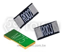
Token (LRC) metal strip current sense chip resistor save space, time, and cost.
Providing design engineers with an economical low ohmic value, metal strip current sense surface mount resistor with high quality performance, Token Electronics LRC Series is suitable for applications in the automotive sector for applications that require high power handling (Up to 3W) and low resistance 0.5mΩ.
From a certified supplier offering the automotive quality, Token's LRC Series gives all round superior performance for current sensing in lamp detection, mirrors, window lift, steering and seat controls.
As a first instance, the LRC Series displays enhanced power handling capabilities, against other technologies.
Thermal conductivity is important for chip resistors - little heat is dissipated directly into the air, and instead, is conducted out through the solder pads.
The heat generated from the specially constructed LRC resistor is more readily dispersed, therefore preventing localised heating, which contributes to TCR and thermal EMF errors, premature aging and possible scorching of the PC board.
The current sensing resistors (LRC) are rated for ambient operation from -55°C to +170°C. The LRC Series is RoHS compliant and lead free.
Downloads Complete Specification PDF (415KB) Metal Strip Chip Current Sense Resistors.
Contact us with your specific needs.
Features :
- Low TCR ±50PPM/°C, ±100PPM/°C.
- High Wattage Rating Up to 3W.
- Customized Resistance Available.
- Resistance Values from 0.5mΩ to 15mΩ.
- Without Laser Trimmed with Very Low Inductance.
Applications :
- For NB power management.
- For MB power management.
- For Monitor power management.
- SWPS: DC-DC converter, Charger, Adaptor.
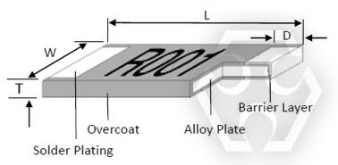
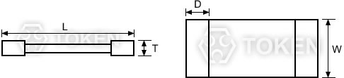
2512 Construction & Dimension (LRC)
|
 Black 2512 - Wave or IR reflow soldering
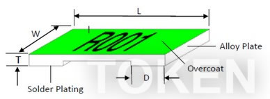 Green 2512 - IR reflow soldering only
1206 & 2010 Construction (LRC)
|
||
| Type | Material | |
| 0M50 ~ R003 | Manganese, Copper | |
| 3M5 ~ R010 | Aluminum, Iron, Chromium | |
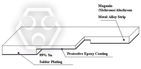 1206 & 2010 Construction
Chip 2512, 2010, 1206 Dimensions (LRC)
|
|||||||
| Type | Resistance (mΩ) | L(mm) | W(mm) | T(mm) | D(mm) | Weight(g) / 1000pcs | |
| LRC06*TF0M50 | 0.50 | 3.20±0.25 | 1.60±0.10 | 0.60±0.20 | 1.35±0.25 | 22.6 | |
| LRC06*TD0M75 | 0.75 | 3.20±0.25 | 1.60±0.10 | 0.60±0.20 | 1.23±0.25 | 22.6 | |
| LRC06*T***** | 1.0, 3.5, 4.0, 5.0, 6.0 | 3.20±0.25 | 1.60±0.10 | 0.60±0.20 | 1.10±0.25 | 22.6 | |
| LRC06*T***** | 2.0, 3.0, 10 | 3.20±0.25 | 1.60±0.10 | 0.60±0.20 | 0.60±0.25 | 22.6 | |
| LRC06*T***** | 1.2, 1.5, 7.0, 8.0, 9.0 | 3.20±0.25 | 1.60±0.10 | 0.60±0.20 | 0.90±0.25 | 22.6 | |
| LRC10*TEA0M50 | 0.5 | 5.08±0.25 | 2.54±0.15 | 0.60±0.20 | 2.17±0.25 | 42.3 | |
| LRC10*TDA0M75 | 0.75 | 5.08±0.25 | 2.54±0.15 | 0.60±0.20 | 2.04±0.25 | 42.3 | |
| LRC10*TDAR001 | 1.0 | 5.08±0.25 | 2.54±0.15 | 0.60±0.20 | 1.84±0.25 | 42.3 | |
| LRC10*TDA**** | 2.0, 6.0, 7.0, 8.0 | 5.08±0.25 | 2.54±0.15 | 0.60±0.20 | 1.54±0.25 | 42.3 | |
| LRC10*TDAR003 | 3.0 | 5.08±0.25 | 2.54±0.15 | 0.60±0.20 | 1.04±0.25 | 42.3 | |
| LRC10*TDA**** | 4.0, 5.0 | 5.08±0.25 | 2.54±0.15 | 0.60±0.20 | 1.84±0.25 | 42.3 | |
| LRC10*TDA**** | 9.0, 10 | 5.08±0.25 | 2.54±0.15 | 0.60±0.20 | 1.29±0.25 | 42.3 | |
| LRC12*T**0M50G | 0.50 | 6.35±0.25 | 3.00±0.20 | 0.60±0.20 | 2.68±0.25 | 59.13 | |
| LRC12*T**0M75G | 0.75 | 6.35±0.25 | 3.00±0.20 | 0.60±0.20 | 2.48±0.25 | 59.13 | |
| LRC12*T******G | 1.0, 6.0 | 6.35±0.25 | 3.00±0.20 | 0.60±0.20 | 1.93±0.25 | 59.13 | |
| LRC12*T******G | 1.5, 6.5, 7.0 | 6.35±0.25 | 3.00±0.20 | 0.60±0.20 | 1.43±0.25 | 59.13 | |
| LRC12*T******G | 2.0, 2.5, 3.0, 3.5 | 6.35±0.25 | 3.00±0.20 | 0.60±0.20 | 1.18±0.25 | 59.13 | |
| LRC12*T******G | 4.0, 4.5 | 6.35±0.25 | 3.00±0.20 | 0.60±0.20 | 2.18±0.25 | 59.13 | |
| LRC12*T******G | 5.0, 6.0 | 6.35±0.25 | 3.00±0.20 | 0.60±0.20 | 1.93±0.25 | 59.13 | |
| LRC12*T******G | 8.0 - 10 | 6.35±0.25 | 3.00±0.20 | 0.60±0.20 | 1.18±0.25 | 59.13 | |
| LRC12*T*****G | 11 - 15 | 6.35±0.25 | 3.00±0.20 | 0.60±0.20 | 1.18±0.25 | 59.13 | |
| LRC12*T*0M50 | 0.50 | 6.35±0.254 | 3.18±0.254 | 1.25±0.20 | 1.30±0.38 | 184.11 | |
| LRC12*T*0M75 | 0.75 | 6.35±0.254 | 3.18±0.254 | 0.75±0.20 | 1.30±0.38 | 131.11 | |
| LRC12*T*R001 | 1.00 | 6.35±0.254 | 3.18±0.254 | 0.65±0.20 | 1.30±0.38 | 110.85 | |
| LRC12*T*1M50 | 1.50 | 6.35±0.254 | 3.18±0.254 | 0.45±0.20 | 1.30±0.38 | 67.16 | |
| LRC12*T*R002 | 2.00 | 6.35±0.254 | 3.18±0.254 | 0.35±0.20 | 1.30±0.38 | 49.30 | |
| LRC12*T*2M50 | 2.50 | 6.35±0.254 | 3.18±0.254 | 0.65±0.20 | 1.30±0.38 | 97.95 | |
| LRC12*T*R003 | 3.00 | 6.35±0.254 | 3.18±0.254 | 0.55±0.20 | 1.30±0.38 | 83.49 | |
| LRC12*T*R004 | 4.00 | 6.35±0.254 | 3.18±0.254 | 0.45±0.20 | 1.30±0.38 | 62.59 | |
| LRC12*T*R005 | 5.00 | 6.35±0.254 | 3.18±0.254 | 0.35±0.20 | 1.30±0.38 | 49.84 | |
| LRC12*T*R006 | 6.00 | 6.35±0.254 | 3.18±0.254 | 0.32±0.20 | 1.30±0.38 | 41.76 | |
| LRC12*T*6M50 | 6.50 | 6.35±0.254 | 3.18±0.254 | 0.30±0.20 | 1.30±0.38 | 35.85 | |
| LRC12*T*R007 | 7.00 | 6.35±0.254 | 3.18±0.254 | 0.27±0.20 | 1.30±0.38 | 34.01 | |
| LRC12*T*R010 | 10.00 | 6.35±0.254 | 3.18±0.254 | 0.25±0.20 | 1.30±0.38 | 25.97 | |
 Chip 2512, 2010, 1206 Dimensions (LRC)
Notice : TOKEN is capable of manufacturing the optional spec based on customer's requirement.
Standard Electrical Specifications (LRC)
| Type | Power Rating at 70°C | Operating Temp. Range | Resistance Tolerance (±%) | Resistance (mΩ) | TCR (±PPM/°C) |
| LRC06*TF0M50 | 1W | -55°C ~ +170°C | ±1, ±3, ±5 | 0.5 | ±200 |
| LRC06*TD**** | 1W | 0.75 - 10 | ±50 | ||
| LRC12*TD**** | 1W | 0.5, 0.75, 1, 1.5, 2 | ±50 | ||
| LRC12*TW**** | 1W | 6, 6.5, 7 | ±75 | ||
| LRC12*TE**** | 1W | 4, 5, 10 | ±100 | ||
| LRC12*TK**** | 1W | 2.5, 3 | ±150 | ||
| LRC12*TD****G | 1W | 11, 12, 13, 14, 15 | ±50 |
High Power Rating Electrical Specifications (LRC)
| Type | Power Rating at 70°C | Operating Temp. Range | Resistance Tolerance (±%) | Resistance (mΩ) | TCR (±PPM/°C) |
| LRC10*TEA0M50 | 1.5W | -55°C ~ +170°C | ±1, ±3, ±5 | 0.5 | ±100 |
| LRC10*TDA**** | 1.5W | 0.75 - 10 | ±50 | ||
| LRC12*TDS**** | 2W | 0.5, 0.75, 1, 1.5, 2 | ±50 | ||
| LRC12*TWS**** | 2W | 6, 6.5, 7 | ±75 | ||
| LRC12*TES**** | 2W | 4, 5, 10 | ±100 | ||
| LRC12*TKS**** | 2W | 2.5, 3 | ±150 | ||
| LR1C2*TDS****G | 2W | 6.5, 7, 8, 9, 10 | ±50 | ||
| LRC12*TDB****G | 2.5W | 4, 4.5, 5, 6 | ±50 | ||
| LRC12*TDR****G | 3W | 1, 1.5, 2, 2.5, 3, 3.5 | ±50 | ||
| LRC12*TER****G | 3W | 0.5, 0.75 | ±100 |
Remark : Operating Current I = √ ( P / R ) , Operating Voltage V = √ ( P * R )
Environmental Characteristics (LRC)
| Item | Specification | Test Method | |
| Black coating | Green coating | ||
| Thermal Shock | ±0.5% |
±1% |
-55°C~150°C, 100 cycles. MIL-STD-202 Method 107G |
| Short Time Overload | ±0.5% |
±1% |
5*Rated Power for 5 seconds. JIS-C-5202-5.5 |
| Endurance | ±1% |
±1% |
70±2°C, Max. working voltage for 1000 hrs with 1.5 hrs and 0.5 hrs |
| Dry Heat | ±1% |
±1% |
at +170°C for 1000 hrs |
| Resistance to Soldering Heat | ±0.5% |
±1% |
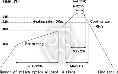
260±5°C, for 10 seconds. MIL-STD-202F Method 210E |
| Solderability | 95% min coverage |
245±5°C for 3 seconds. MIL-STD-202F Method 210E | |
| Temperature Coefficient of Resistance | As Spec. |
+25/-55/+25/+125/+25°C. MIL-STD-202 Method 304 | |
|
Soldering Condition (LRC)
|
 Green coating ”Reflow Air Convection” is available
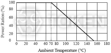
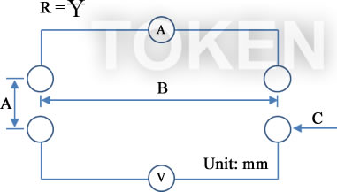
4-Wire Precision Measurement (LRC)
| Figure | Type | A | B | C | Excitation Current (A) | Resistance (Ω) |
 4-Wire Precision Measurement |
LRC12 Black Coating | 1.5 | 5.4 | Φ0.5 | 3A | 0.5m ~ 1.5 m |
| LRC12 Black Coating | 1.5 | 5.4 | Φ0.5 | 1A | 2m ~10m | |
| LRC12 Green Coating | 1.5 | 5.4 | Φ0.5 | 3A | 0.5m ~ 1.5m | |
| LRC12 Green Coating | 1.5 | 5.4 | Φ0.5 | 1A | 2m ~ 15m | |
| LRC06 | 1.25 | 2.6 | Φ0.5 | 3A | 0.5m ~ 1.5m | |
| LRC06 | 1.25 | 2.6 | Φ0.5 | 1A | 2m ~ 10m | |
| LRC10 | 1.2 | 4.32 | Φ0.5 | 3A | 0.5m ~ 1.5m | |
| LRC10 | 1.2 | 4.32 | Φ0.5 | 1A | 2m ~ 10m |
- Note: Equipment: ADEX AX-1152D DC Low Ohm Meter
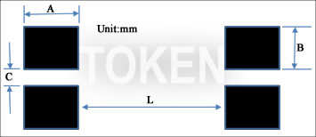
4-Wire Pad Layout (LRC)
| Figure | Type | Resistance (Ω) | A | B | C | L |
 4-Wire Pad Layout |
LRC12 Black Coating | - | 1.0 | 2.7 | 2.95 | 1.45 |
| LRC12 Green Coating | 0M50 | 3.13 | 1.2 | 1.0 | 0.52 | |
| 0M75 | 2.93 | 1.2 | 1.0 | 0.94 | ||
| R001 | 2.38 | 1.2 | 1.0 | 2.04 | ||
| 1M5 | 1.88 | 1.2 | 1.0 | 3.04 | ||
| R002~3M5 | 1.63 | 1.2 | 1.0 | 3.54 | ||
| R004~4M5 | 2.63 | 1.2 | 1.0 | 1.54 | ||
| R005~R006 | 2.38 | 1.2 | 1.0 | 2.04 | ||
| 6M5~R007 | 1.88 | 1.2 | 1.0 | 3.04 | ||
| R008~R015 | 1.63 | 1.2 | 1.0 | 3.54 | ||
| LRC10 | 0M50 | 2.61 | 1.045 | 0.8 | 0.60 | |
| 0M75 | 2.49 | 1.045 | 0.8 | 0.80 | ||
| R001 | 2.29 | 1.045 | 0.8 | 0.95 | ||
| R002 | 1.99 | 1.045 | 0.8 | 1.55 | ||
| R003 | 1.49 | 1.045 | 0.8 | 2.55 | ||
| R004~R005 | 2.29 | 1.045 | 0.8 | 0.95 | ||
| R006~R008 | 1.99 | 1.045 | 0.8 | 1.55 | ||
| R009~R010 | 1.74 | 1.045 | 0.8 | 2.05 | ||
| LRC06 | 0M50 | 1.80 | 0.7 | 0.5 | 0.55 | |
| 0M75 | 1.68 | 0.7 | 0.5 | 0.55 | ||
| R001 | 1.55 | 0.7 | 0.5 | 0.55 | ||
| 1M2 | 1.35 | 0.7 | 0.5 | 0.95 | ||
| 1M5 | 1.35 | 0.7 | 0.5 | 1.55 | ||
| R002~R003 | 1.05 | 0.7 | 0.5 | 1.55 | ||
| 3M5~R006 | 1.55 | 0.7 | 0.5 | 0.55 | ||
| R007~R009 | 1.35 | 0.7 | 0.5 | 0.95 | ||
| R010 | 1.05 | 0.7 | 0.5 | 1.55 |
- Note: No circuits between pads to avoid short circuit
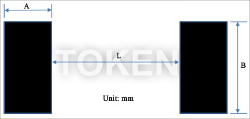
2-Wire Pad Layout (LRC)
| Figure | Type | Resistance (Ω) | A | B | L |
 2-Wire Pad Layout |
LRC12 Black Coating | - | 2.7 | 3.6 | 2.95 |
| LRC12 Green Coating | 0M50 | 3.13 | 3.4 | 0.52 | |
| 0M75 | 2.93 | 3.4 | 0.94 | ||
| R001 | 2.38 | 3.4 | 2.04 | ||
| 1M5 | 1.88 | 3.4 | 3.04 | ||
| R002~3M5 | 1.63 | 3.4 | 3.54 | ||
| R004~4M5 | 2.63 | 3.4 | 1.54 | R005~R006 | 2.38 | 3.4 | 2.04 | 6M5~R007 | 1.88 | 3.4 | 3.04 | R008~R015 | 1.63 | 3.4 | 3.54 | LRC10 | 0M50 | 2.61 | 2.89 | 0.60 |
| 0M75 | 2.49 | 2.89 | 0.80 | ||
| R001 | 2.29 | 2.89 | 0.95 | ||
| R002 | 1.99 | 2.89 | 1.55 | ||
| R003 | 1.49 | 2.89 | 2.55 | ||
| R004~R005 | 2.29 | 2.89 | 0.95 | ||
| R006~R008 | 1.99 | 2.89 | 1.55 | ||
| R009~R010 | 1.74 | 2.89 | 2.05 | ||
| LRC06 | 0M50 | 1.80 | 1.90 | 0.55 | |
| 0M75 | 1.68 | 1.90 | 0.55 | ||
| R001 | 1.55 | 1.90 | 0.55 | ||
| 1M2 | 1.35 | 1.90 | 0.95 | ||
| 1M5 | 1.35 | 1.90 | 1.55 | ||
| R002~R003 | 1.05 | 1.90 | 1.55 | ||
| 3M5~R006 | 1.55 | 1.90 | 0.55 | ||
| R007~R009 | 1.35 | 1.90 | 0.95 | ||
| R010 | 1.05 | 1.90 | 1.55 |
- Note: No circuits between pads to avoid short circuit
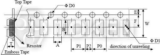
Emboss Plastic Tape Specifications (LRC)
| ||||||||||||||
| Type | Resistance (mΩ) |
A (mm) | B (mm) | W (mm) | E (mm) | F (mm) | P0 (mm) | P1 (mm) | P2 (mm) | ΦD0 (mm) | ΦD1 (mm) | T (mm) | Quantity (Pcs) |
|
| LRC06 | 0.5 - 10 | 1.90±0.1 | 3.60±0.1 | 8.0±0.2 | 1.75±0.1 | 3.5±0.05 | 4.0±0.1 | 4.0±0.1 | 2.0±0.05 | 1.55±0.05 | 1.0min | 0.87±0.1 | 2,000 | |
| LRC10 | 0.5 - 10 | 2.85±0.1 | 5.55±0.1 | 12.0±0.2 | 1.75±0.1 | 5.5±0.05 | 4.0±0.1 | 4.0±0.1 | 2.0±0.05 | 1.55±0.05 | 1.4min | 0.85±0.1 | 2,000 | |
| LRC12 | 0.50 - 0.75 | 3.40±0.1 | 6.75±0.1 | 12.0±0.1 | 1.75±0.1 | 5.5±0.05 | 4.0±0.1 | 4.0±0.1 | 2.0±0.05 | 1.55±0.05 | 1.4min. | 1.45±0.2 | 2,000 | |
| 1 - 10 | 3.40±0.1 | 6.75±0.1 | 12.0±0.1 | 1.75±0.1 | 5.5±0.05 | 4.0±0.1 | 4.0±0.1 | 2.0±0.05 | 1.55±0.05 | 1.4min. | 0.81±0.1 | 2,000 | ||
| LR12 (G) | 0.50 - 15 | 3.40±0.1 | 6.75±0.1 | 12.0±0.1 | 1.75±0.1 | 5.5±0.05 | 4.0±0.1 | 4.0±0.1 | 2.0±0.05 | 1.55±0.05 | 1.4min | 0.85±0.1 | 2,000 | |
 Emboss Plastic Tape Specifications
| Notice : | 1. The cumulative tolerance of 10 sprocket hole pitch is ±0.2mm. |
Order Codes (LRC)
| LRC | 12 | H | TR | D | R011 | G | ||||||||||||||||||||||||||||||||||||||||||||||||||||||||||||||||||||||||
| 1 | 2 | 3 | 4 | 5 | 6 | 7 | 8 | |||||||||||||||||||||||||||||||||||||||||||||||||||||||||||||||||||||||
|
|
|
|
|
|
|
|
|||||||||||||||||||||||||||||||||||||||||||||||||||||||||||||||||||||||
Resistance codes example (3 Marking)
| Resistance | 0.39mΩ | 0.5mΩ | 0.75mΩ | 330mΩ | 5.1Ω |
| Codes | M39 | M50 | M75 | R33 | 5R1 |
Resistance codes example (4 Marking)
| Resistance | 1mΩ | 1.5mΩ | 2mΩ | 7mΩ | 10mΩ |
| Codes | R001 | 1M50 | R002 | R007 | R010 |