Precision High-Value Voltage Resistors, Hi-Meg Dividers
Cost Effective Complete Selection of High Voltage Components
Token high voltage series can be specified for use in industrial and general purpose high voltage systems, as well as a complete selection of high resistance, Hi-Meg, high-voltage, high frequency, and bulk ceramic resistors for higher average power dissipation. These High Resistance, High Frequency, High Resistance resistors combine the proven performance of Token resistance system with new cost efficient design elements and high voltage applications.
Detailed specifications, both mechanical and electrical, please contact our sales representative for more information.
High Voltage Applications
Resistors produced from Serpentine Pattern Screen Printing Design or bulk ceramic materials have displayed several key advantages in demanding high-voltage situations, including both continuous-wave and pulse applications. These include radar and broadcast transmitters, x-ray systems, defibrillators, lasers, and high-voltage semiconductor process equipment applications, where resistors must handle peak voltage anywhere from 8KV to 75KV.
Typical applications include current limit in capacitor charge/discharge, crowbar, and tube-arc circuits. In these uses, bulk ceramic resistors provide low inductance, high average power per unit size, stability at high voltage, and durability at extreme peak-power levels. Film resistors typically cannot withstand high-voltage pulse applications.
RF/Digital Loads and High-Frequency Applications
Token Non-Inductive Voltage Resistors are used extensively for high-frequency RF loads in broadcast and communication equipment because of their non-inductive characteristics. They provide excellent non-inductive power-handling capacity at frequencies upto the gigahertz range, with no sacrifice in power dissipation.
Film resistors may provide the needed non-inductive characteristics required by such RF applications, but they have size limitations and present reliability problems due to potential film burnout. This is especially true in advanced digital applications such as digital radio and TV transmitters involving pulses at high frequencies.
Application Notes
- Due to the high voltage which can appear between the end cap and any adjacent metal part,
resistors should be mounted at an adequate distance from other conductors. - An appropriate number of resistors may be screwed together as a stick to provide an assembly
which will be capable to withstanding any desired voltage, providing no individual resistor is subject to a greater stress
or power dissipation than is recommended in its data sheet, and that appropriate anticorona devices are fitted. - The axial termination should not be bent closer than twice the diameter of the terminal wire from the body of the resistor.
When resistors are required to be potted, the preferred encapsulant is a silicone compound. - The use of in the air, the most likely because of air humidity or resistance to damp caused by the parallel resistance,
resulting in the reduction of total resistance and withstand voltage and burn resistor, must be sealed resin for damp-proof. - For the full load of the operating voltage, must be sealed resin or immersed in high-pressure oil used.
However, it should be noted that any single resistor does not recommend the use of the power consumption greater than Rated Power. - The application design of high voltage resistor, the power of long time safe use is below 25% Rated Power.
Oil Immersion
For some high voltage applications it is required to immerse the components in oil or gas to reduce the effects of corona and surface tracking. A special lacquer protected version of the resistor is available, suitable for immersion in transformer oil or SF6.
Download General Info. of High Voltage Resistors in PDF file.
PDF Catalogue
Download Entire High Voltage Resistor Catalogue in PDF file (940KB).
High Voltage, High Resistance, High Frequency
ThumbnailType and Description Power Rating (W) Resistance (Ω) Max. Voltage (V)
-
1 (HM) Non-magnetic Precision High-Value Chip Resistors
 0.05W ~ 1.5W 100Ω ~ 10TΩ 30V ~ 6KV
Token non-magnetic chip resistor (HM) series, applied to the field of medical high magnetic fields, such as electronic circuits located in magnetic resonance (MRI) and computed tomography (CT), or in the extreme environment of oil and gas industries, such as downhole instruments for oil wells, or flight control in aerospace applications.
0.05W ~ 1.5W 100Ω ~ 10TΩ 30V ~ 6KV
Token non-magnetic chip resistor (HM) series, applied to the field of medical high magnetic fields, such as electronic circuits located in magnetic resonance (MRI) and computed tomography (CT), or in the extreme environment of oil and gas industries, such as downhole instruments for oil wells, or flight control in aerospace applications.
Download (HM) PDF -
2 (HI80) Ultra-Precision High-Power High-Voltage Resistors
0.8W ~ 300W 1Ω ~ 10GΩ 3KV ~ 80KV
(HI80) family includes (HI80P) high-power high-voltage resistors, (HI80DS) conventional miniaturized high-voltage resistors , (HI80D) conventional high-voltage resistors, and (HI80T) ultra-precision high-voltage resistors. It is specifically designed for general purpose industrial high voltage system applications.
Download (HI80) PDF -
3 (HI82) Planar Ultra-Precision High Voltage Film Resistors
1W ~ 3W 1MΩ ~ 10TΩ 10KV ~ 30KV
Token Electronics has introduced ultra-stable high-precision HI82 high voltage resistors to meet these needs. The high performance high-voltage applications require the use of high voltage resistors in applications with long-term stability and good temperature coefficient.
Download (HI82) PDF -
4 (HI83) Thick Film Planar Dividers, High Voltage Resistors
1/4W ~ 5W 10KΩ ~ 1GΩ 6KV ~ 25KV
The planar thick film divider resistor (HI83) provides stable performance over a wide range of resistance values with a voltage rating up to 35KV. The maximum resistance ratio is 1000: 1 (ratio greater than 1000: 1, such as 2000: 1, 4000: 1, and 5000: 1 is available on request) with a minimum resistance ratio of 40: 1.
Download (HI83) PDF -
5 (RI80) Impulse High Voltage Resistors 1W ~ 300W 1MΩ ~ 1000MΩ 10KV ~ 35KV Metal Glaze Impulse Resistor RI80 Series are able to absorb large amounts of energy at high voltage while remaining non-inductive. Ideal for: Capacitor crowbar circuits, Impulse voltage generators, Energy research, Pulse modulators, Radar Pulse-forming networks, High voltage snubber circuits, Arc furnace damping, X-ray/imaging equipment, and EMI/lightning supression.
Download (RI80) PDF (471KB) -
6 (CCR) High pulse withstanding carbon composition resistor 1/2W ~ 1/4W 1Ω ~ 100MΩ - Carbon composition resistor CCR series are excellent characteristic against high voltage surge current. Higher reliability for disconnection failure comparing to wirewound and film series.
Download (CCR) PDF (434KB) -
7 (RI85) Power High Voltage Resistors 200W ~ 800W 100KΩ ~ 10TΩ 50KV ~ 100KV The RI85 Power High Voltage Resistor uses Token's proprietary thick film metal glaze resistive element and Serpentine Pattern Design which provides ideal cost efficient, stability, high power and high voltage characteristics for a wide range of measurement, voltage divider circuits, and control functions in high voltage power electronics applications.
Download (RI85) PDF (434KB) -
8 (NTK) Network High Voltage Dividers 0.3W ~ 5W Custom 500V ~ 10KV By applying this technology to the low-profile Network High Voltage Divider, single-in-line package configuration, the Type (NTK) Custom SIP Resistor Voltage Divider Networks are available with a combination of features. which include: Low TCR 250 ppm/°C (100 ppm/°C or tighter upon request), operating temperature range -55°C ~ +125°C (higher temperature upon request), flat style, non-inductive, low noise, and also custom divider design.
Download (NTK) PDF (292KB) -
9 (RI82) Precision High Voltage Resistors 0.125W ~ 30W 10MΩ ~ 1KKMΩ 4KV ~ 30KV The High Voltage RI82 Precision Resistor use Token's proprietary thick film Metal Glaze resistive element and Serpentine Pattern Design which provides ideal cost efficient, stability, precision, non-Inductive, and high voltage characteristics for a wide range of measurement, voltage divider circuits, and control functions in high voltage power electronics applications.
Download (RI82) PDF (372KB) -
10 (RY31A) High Voltage High Frequency Resistors 10W ~ 150W 50Ω ~ 75Ω 3.2KV ~ 12.5KV RY31A high voltage high frequency Resistor, with the inner and outer surfaces coated with a special glass, features higher thermal resistance oxide film and larger electric power capacity for the compact volume. Unlike conventional wire wound type, the volumetric resistance will provide superior stability versus frequency and excellent durability against transient voltage. RY31A is suitable for the application with large current as well as high frequency circuit.
Download (RY31A) PDF (297KB) -
11 (RH1) Hermetic Hi-Meg Resistors 1/2W 10MΩ ~ 1TΩ 1000V The RH1 Hermetic Hi-Meg Resistor is disclosed as being encapsulated in a glass tube, the enclosure being hermetically sealed to conductive caps mounted on the resistor ends. The metal glaze film of the resistance path of the resistor is protected from thermal damage during heat sealing by spacing the resistance path from the conductive caps and providing an electrical path there between in the form of an extended termination.
Download (RH1) PDF (319KB) -
12 (RMCA, RMCB) High Voltage Ceramic Composition Resistors 1W ~ 5W 470Ω ~ 100KΩ 300V ~ 500V Token's RMCA, RMCB Ceramic Composition Resistor now offers the industry a direct replacement carbon composition resistor based on a bulk resistive element comprising carbon in a ceramic filler. Due to the need for higher peak voltages, the RMCA, RMCB range is perfect for vehicle ignition system applications.
Download (RMCA, RMCB) PDF (357KB) -
13 (RMCC) Metal Ceramic Resistors 1W ~ 5W 470Ω ~ 100KΩ 300V ~ 500V Following market demands, Token Electronics provided an extent of Bulk Ceramic Composition RMCA, RMCB Series to RMCC axail lead Metal Ceramic Resistor. The cap and lead assemblies are pressed onto the RMCC resistor core, finishing the resistor and providing rugged terminal attachment.
Download (RMCC) PDF (367KB) -
14 (RCR) Anti-Surge Pulse Load Resistors 0.25W ~ 10W 1Ω ~ 100MΩ 500V ~ 3KV Anti-Surge Pulse Load Resistor RCR series is made by metal glaze coating on the surface of a cylindrical substrate with excellent characteristics and stable at even high resistance range.
Download (RCR) PDF (333KB) -
15 (RMCD) Ceramic Tubular High Voltage Resistors 35W ~ 100W 75Ω ~ 1KΩ 15KV ~ 75KV This Ceramic Tubular Resistor RMCD offer higher average power dissipation while retaining the advantages of high surge energy, high voltage withstand, and non-inductance. It is especially useful in RF applications such as transmitters and modulators, where the tube configuration provides more effective convection cooling.
Download (RMCD) PDF (331KB)
Terminology & Glossary
Cermet
A cermet resistive element is made from a mixture of glass and metal oxides. The metal oxide is typically RuO2 or an AgPt alloy. Applying cermet materials to a flat or cylindrical substrate, and then firing them at 850°C produce thick Film resistors. In the electronic industry cermet material is typically called Thick Film paste or ink.
Critical Resistance Value
The maximum nominal resistance value at which the rated power can be applied continuously without exceeding the maximum working voltage is the critical resistance value. The rated voltage is equal to the maximum working voltage in the critical resistance value. If the circuit designs permits, the choice of a high ohmic value resistor or divider network will eliminate this consideration.
Derating Curve
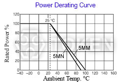
Typical Derating Curve
The curve that describes the relationship between the resistors’s operating temperature and the maximum value of continuous power permitted at that temperature. If the circuit designs permits, the choice of a high ohmic value resistor or divider network will minimize this consideration and improve the resistor's performance because it will operate at lower power.
Maximum Working Voltage
The maximum voltage applied continuously to a resistor or a resistor element. The maximum value of the applicable voltage is the rated voltage at the critical resistance value or lower. If the circuit designs permits, the choice of a high ohmic value resistor or divider network will improve the resistor's performance because it will operate at lower power.
Noise
Resistive noise can have a devastating effect on low-level signals, charge amplifiers, high gain amplifiers, and other applications sensitive to noise. The best approach is to use resistor types with low or minimal noise in applications that are sensitive to noise. Because of their construction and manufacturing processes.
Power Rating
Power ratings are based on physical size, allowable change in resistance over life, thermal conductivity of materials, insulating and resistive materials, and ambient operating conditions. For best results, employ the largest physical size resistors at the less than their maximum rated temperature and power. Never use them continuously at their maximum rating unless you are prepared to accept the maximum allowed life cycle changes. If the circuit designs permits, the choice of a high ohmic value resistor or divider network will minimize the power level and improve the resistor’s performance as it is operating at a lower power level.
Rated Power
Rated power is the maximum value of power (watts), which can be continuously applied to a resistor at a rated ambient temperature. The basic mathematical relationship is Equation: Power (watts) = (Current (Amps))2 × Resistance (Ohms).
If the circuit designs permits, the choice of a high ohmic value resistor or divider network will minimize the power level and improve the resistor’s performance because it is operating at a lower power and temperature level.
Rated Voltage
The maximum voltage applied continuously to a resistor at the rated ambient temperature. Rated voltage is calculated from the following formula, but it must not exceed the maximum working voltage. Equation: Rated Voltage (V) = (Rated Power (W) × Nominal Resistance Value (Ω))1/2.
High voltage resistors often are potted or operated in oil as the arc over voltage, in air, is approximately 10,000 volts per inch. Token's resistors feature higher voltage ratings due to their high square count and associated design characteristics.
Resistor Tolerance
Resistor Tolerance is expressed as the deviation from nominal value in percent and is measured at 25°C only with no appreciable load applied. A resistors value will also change with applied voltage (VCR) and temperature (TCR). For networks, absolute resistor tolerance refers to the overall tolerance of the network. Ratio tolerance refers to the relationship of each resistor to the others. It is often practical to specify tight ratio tolerances and loose absolute tolerances.
Temperature Coefficient of Resistance (TCR)
Typical Thick Film TCR (Temperature Coefficient of Resistance) Curve
The Temperature Coefficient of Resistance (TCR) is expressed as the change in resistance in ppm (0.0001%) with each degree of change in temperature Celsius (°C). For example, a resistor with a TCR of +100 ppm/°C will change +0.1% total over a 10-degree change and +1% total over a 100-degree change.
The TCR value quoted on specification sheets is typically quoted as being referenced at +25°C and is the +25°C to +75°C slope of the TCR curve. TCR is typically not linear, but parabolic with temperature, as illustrated by the accompanying fig-1. Often the circuit designer treats the TCR as being linear unless very accurate measurements are needed. MIL STD 202 Method 304 is often referenced as a standard for measuring TCR. The following formula expresses the rate of change in resistance value per 1 °C in a prescribed temperature range:
- TCR (ppm/°C) = (R - Ro) / Ro × 1 / (T - To) × 106
- R: Measured resistance (Ω) at T °C;
Ro: Measured resistance (Ω) at To °C - T: Measured test temperature (°C);
To: Measured test temperature (°C)
In the context of a resistor network, this TCR value is called the absolute TCR in that it defines the TRC of a specific resistor element.
Voltage Coefficient of Resistance (VCR)
The Voltage Coefficient is the change in resistance with applied voltage. This is entirely different and in addition to the effects of self-heating when power is applied. A resistor with a VCR of 100 ppm/V will change 0.1% over a 10 Volt change and 1% over a 100 Volt change. The rate of change in resistance value per 1 Volt in the prescribed voltage range is expressed by the following formula:
- VCR (ppm/V) = (Ro - R) / Ro × 1 / ( Vo - V) × 106
- R: Measured resistance (Ω) at base voltage; V: Base voltage
- Ro: Measured resistance (Ω) at upper voltage; Vo: Upper voltage
Download Terminology & Glossary in PDF file.