Carbon Composition Resistors
(CCR)Introduction (CCR)
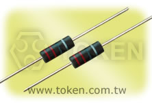
High pulse withstanding carbon composition resistors handle big peaks and pulses.
The high pulse withstanding capability of the CCR series of carbon composition resistors from Token Electronics offers designers a compact solution for applications involving high voltages and high-energy pulses.
Though, many resistor manufacturers claim to offer carbon composition replacements. However, these wirewound or thick film alternatives do not fully match the pulse performance and low inductance of carbon composition.
Token's CCR series now offers the industry a carbon composition resistor made up of a solid rod of conductive composite material, the chemical composition of which is altered to produce different resistance values.
The main advantage of carbon composition is their pulse handling capability. This is due to the fact that the entire rod conducts and so the thermal mass is far higher, which results in a higher energy capability. Due to the need for higher peak voltages, the CCR range is perfect for vehicle ignition system applications, medical monitoring equipment and as output resistors in defibrillators.
The standard carbon composition CCR resistor offers a power rating of 1/4W, 1/2W, 1W and 2W at 25°C and is made up of a solid rod of conductive composition material, which can be altered to produce different resistance values. With a typical resistance range of 1.8Ω ~ 22KΩ, resistance tolerance is J(±5%), K(±10%) and M(±20%). Resistors with 5%, 10% and 20% tolerance have four bands indicating value and tolerance in accordance with IEC62.
Our custom solutions are designed to address your need for technical and economic success in a timely manner.
Contact us with your specific needs.
Features :
- Low inductance
- Solid rod carbon composition
- Power rating 1/4W and 2W
- Resistance range 1.8Ω ~ 22KΩ
- Resistance tolerance J(±5%), K(±10%) and M(±20%)
- High pulse withstanding and high energy capability
- Products with Pb-free Terminations and RoHS compliant
Applications :
- Strobe Lighting
- High Power Lighting
- Medical defibrillators
- Welding, Automotive
- Inrush Current Limiting
- High Voltage Power Supplies
- Protection (e.g. Discharge Circuits, Surge Protection)
Dimensions (Unit: mm) (CCR)
|
|||||||
| Type | Power Rating | L | Φ D | H | Φ d | ||
| CCR | 1/4W | 6.3 | +1.0 | 2.3±0.3 | 27±2 | 0.60±0.02 | |
| -1.0 | |||||||
| CCR | 1/2W | 9.5 | +0.5 | 3.5±0.3 | 27±2 | 0.70±0.02 | |
| -1.5 | |||||||
| CCR | 1W | 15 | +1.5 | 6.0±0.3 | 28±2 | 0.80±0.02 | |
| -0.5 | |||||||
| CCR | 2W | 18 | +0.5 | 8.0±0.3 | 27±2 | 1.00±0.02 | |
| -1.5 | |||||||
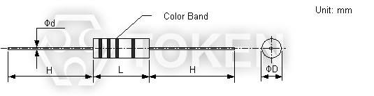 Carbon Composition (CCR) Dimensions (Unit: mm)
Ratings Specifications (CCR)
| Type | Power Rating | Resistance Range | Tolerance E12,E24 | Max Working voltage | Max overload Voltage | Rated Ambient Temp. | Operating Temp. Range |
| CCR | 1/4W | 2.2Ω ~ 12MΩ | J(±5%) K±10% M±20% |
250V | 400V | +70°C | -55°C ~ +125°C |
| CCR | 1/2W | 2.2Ω ~ 22MΩ | 350V | 700V | +70°C | -55°C ~ +125°C | |
| CCR | 1W | 2.2Ω ~ 22KΩ | 500V | 1000V | +70°C | -55°C ~ +125°C | |
| CCR | 2W | 1.8Ω ~ 10KΩ | 500V | 1000V | +70°C | -55°C ~ +125°C |
Rated Voltage = ![]() or Max. working voltage,whichever is lower.
or Max. working voltage,whichever is lower.
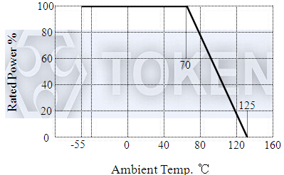
Derating Curve (CCR)
|
Performance (CCR)
| Description | Performance Requirements | Test Method | |||
| Resistance Temperature Coefficient | Resistance Range | Maximum Resistance Value Change % | Test Temperature +20°C /-40°C /+20°C /+100°C /+20°C |
||
| -40~+20°C | +20~+100°C | ||||
| <1KΩ | ±6.5% | ±5.0% | |||
| 1.1KΩ ~10KΩ | ±10% | ±6.0% | |||
| 11KΩ ~100KΩ | ±13% | ±7.5% | |||
| 11KΩ ~1MΩ | ±15% | ±10% | |||
| 1.1MΩ ~10MΩ | ±20% | ±15% | |||
| >11MΩ | ±25% | ±20% | |||
| Short-time Overload | Δ R≤±2.5% | Rate Voltage*2.5 or maximun overload voltage (the lower)5sec. | |||
| With Standing Voltage | No flashover or breakdown | 2times maxium working voltage 1 minute | |||
| Terminal Strength | Pulled | ΔR≤±2% No visible damage | Load 10N 10s | ||
| Winded | Load 10N 4*90° | ||||
| Twisted | 3*360° in opposite direction | ||||
| Resistance to vibration | No visible damage | 10~50Hz 3 direction 2 hours each | |||
| Solder-heat Resistance | ΔR≤±5% Marks legible,no visible damage | 350°C 4mm from the body,3 seconds | |||
| Solderability | At least 95% if the dipping surface must be covered by new solder,no flaws gathered. | 235°C 2mm from the body,2 seconds | |||
| Temperature Cycle | ΔR≤±2% No visible damage |
-40°C(30min.)/85°C(30min.)5 cycles | |||
| Humidity | ΔR≤±10% No visible damage | 40°C 95% RH 240 hours | |||
| Load Life | ΔR≤±10% No visible damage,marks legible |
Rated voltage or maximum working voltage, 1.5 hours on, 0.5 hours off, 40°C 1000 hours | |||
Order Codes (CCR)
| CCR | 1/2W | 120R | K | P | |||||||||||||||||||||||||
| 1 | 2 | 3 | 4 | 5 | |||||||||||||||||||||||||
|
|
|
|
|
|||||||||||||||||||||||||
More Information of Resistors in PDF Download
High Pulse Withstanding Carbon Composition Resistors (CCR) PDF download (327KB).
What is a Resistor PDF download (562KB).
Typical RoHS Reflow Profile PDF download (303KB).
Resistor Precautions in Usage PDF download (301KB).
Common Resistor Terminology PDF download (315KB).
Resistor Glossary & Terminology PDF download (219KB).
Selecting The Optimum Resistors PDF download (234KB).
Token Resistor Color Coding System PDF download (379KB).
Resistor Lead Forming and Dimensions PDF download (260KB).
Information of General Purpose Resistors PDF download (214KB).
General Purpose, Wire Wound, Fusible Resistor Series PDF download (1,178KB).