Surface Mount Chip Resistors, SMD Resistors
Surface Mount Chip Resistors


Low Value Current-Sensing Chips


Surface Mount Terminology & Glossary
Selecting the optimum chip technology necessary to best match the performance requirements
Surface mount resistors are main key of electronic components composed electronic circuit. Chips are developed with demands of diverse electronic circuits and used. To summarize the application technique about surface mount resistors use for electric machine and tools, especially, which need high density mount in these chips. To make the best fit selection of chip resistors, in general, confirm with the characteristic of that circuit, as following steps:
- Single chip resistor or Composite chip resistor;
- For single chip resistor, there is an option of thick-film chip or thin-film chip;
- For composite chips, there is another option of chip resistor array (common terminal circuit) or chip resistor network (isolated circuit);
- For applications required pulse withstanding, working voltage ratings (power wattage) is one of key factors.
- For applications required stability and precision, look for Token's Electrical Specifications for TCR and Resistance Tolerance parameters.
Whether you’re designing circuit for telecommunications, computers, consumer electronics or office equipment, Token has the right chips for your application.
Temperature Coefficient of Resistance (TCR)
Fig-1 Typical TCR (Temperature Coefficient of Resistance) Curve
The Temperature Coefficient of Resistance (TCR) is expressed as the change in resistance in ppm (0.0001%) with each degree of change in temperature Celsius (°C). For example, a resistor with a TCR of +100 ppm/°C will change +0.1% total over a 10-degree change and +1% total over a 100-degree change.
The TCR value quoted on specification sheets is typically quoted as being referenced at +25°C and is the +25°C to +75°C slope of the TCR curve. TCR is typically not linear, but parabolic with temperature, as illustrated by the accompanying fig-1. Often the circuit designer treats the TCR as being linear unless very accurate measurements are needed. MIL STD 202 Method 304 is often referenced as a standard for measuring TCR. The following formula expresses the rate of change in resistance value per 1 °C in a prescribed temperature range:
- TCR (ppm/°C) = (R - Ro) / Ro × 1 / (T - To) × 106
- R: Measured resistance (Ω) at T °C; Ro: Measured resistance (Ω) at To °C
- T: Measured test temperature (°C); To: Measured test temperature (°C)
In the context of a resistor network, this TCR value is called the absolute TCR in that it defines the TRC of a specific resistor element.
Rated Voltage
The maximum voltage applied continuously to a resistor at the rated ambient temperature. Rated voltage is calculated from the following formula, but it must not exceed the maximum working voltage. Equation: Rated Voltage (V) = (Rated Power (W) × Nominal Resistance Value (Ω))1/2
High voltage resistors often are potted or operated in oil as the arc over voltage, in air, is approximately 10,000 volts per inch. Token’s resistors feature higher voltage ratings due to their high square count and associated design characteristics.
Catalogue Download
Download Surface Mount Terminology & Glossary in PDF file.
ESD Sensitivity of Chips
The sensitivity level of resistors used in electronic equipment to an electrostatic discharge (ESD) varies from a few hundred volts to a few tens of kilovolts. Ways to make resistors more robust to ESD are suggested.
The most popular electronic assembly method today is the surface mount technology, SMT. Manufacturers of components responded to this trend by developing standard sizes of surface mounted chips. Miniaturization leads to the use of smaller sized SMT chips and this causes an increase in the sensitivity of electronic equipment to ESD. ESD voltage levels which do not affect larger resistor chips may be dangerous for smaller sizes because of their smaller heat capacity.
Therefore, resistance value by ESD characteristic tends to become large following on becoming small. Moreover, it is influenced by conductive mechanism of resistive material, resistance value trends to be influenced with the range from 100 Ω to 100k Ω, and the ESD characteristic is hard to be influenced by ESD in the domain where resistance value is lower than that range or a high domain.
The Difference between Thin Film and Thick Film Chips
The principal difference between thick film and thin film resistors is not the actual thickness of the film, but rather how the film is applied to the chip substrate surface (SMD resistors) or the cylinder (axial resistors).
Thin film resistors are made by sputtering (a method of vacuum deposition) the resistive material onto an insulating substrate. The film is then etched in a similar manner to the old (subtractive) process for making printed circuit boards; that is, the surface is coated with a photo-sensitive material, then covered by a pattern film, irradiated with ultraviolet light, and then the exposed photo-sensitive coating is developed, and underlying thin film is etched away.
Thick Film Resistor is manufactured by screen-printed a much thicker conductive paste of Ceramic and Metal, called Cermet, onto an alumina ceramic substrate. This composite of glass and conductive ceramic (cermet) material is then baked in an oven at about 850 °C to form the film.
Thin film resistor has better TCR and tighter tolerance than thick film due to sputtering technology precision timing control while thick film resistor has better pulse withstanding ability than thin film because of the thickness of film.
Power Rating
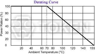
Fig-2 Power Derating Curve
Power ratings are based on physical size, allowable change in resistance over life, thermal conductivity of materials, insulating and resistive materials, and ambient operating conditions. For best results, employ the largest physical size resistors at the less than their maximum rated temperature and power. Never use them continuously at their maximum rating unless you are prepared to accept the maximum allowed life cycle changes. If the circuit designs permits, the choice of a high ohmic value resistor or divider network will minimize the power level and improve the resistor’s performance as it is operating at a lower power level.
Rated Power
Rated power is the maximum value of power (watts), which can be continuously applied to a resistor at a rated ambient temperature. The basic mathematical relationship is Equation: Power (Watts) = (Current (Amps))2 × Resistance (Ohm).
If the circuit designs permits, the choice of a high ohmic value resistor or divider network will minimize the power level and improve the resistor’s performance because it is operating at a lower power and temperature level.
Maximum Working Voltage
The maximum voltage applied continuously to a resistor or a resistor element. The maximum value of the applicable voltage is the rated voltage at the critical resistance value or lower. If the circuit designs permits, the choice of a high ohmic value resistor or divider network will improve the resistor’s performance because it will operate at lower power.
Surface Mount Component Application Notes
Safety Precautions
- Avoid excessive bending of printed circuit boards in order to protect the resistors from abnormal stress
- When soldering with a soldering iron, never touch the body of chip resistor with the tip of the soldering iron.
When using a soldering iron with a high temperature tip, finish soldering as quickly as possible (within three seconds at 350 °C max.) - Take measures against mechanical stress during and after mounting of Chips, so as not to damage their electrodes and protective coatings.
Be careful not to misplace the resistors on the land patterns. Otherwise, solder bridging may occur - If a transient load like a pulse is expected to be applied, check and evaluate the operations of the resistors before use.
Never exceed the rated power. Otherwise, the performance and reliability of the chip device may be damaged - As the amount of applied solder becomes larger, the mechanical stress applied to the resistors increases,
causing problems such as cracks and faulty characteristics. Avoid applying an excessive amounts of solder - Do not apply shock to the resistors or pinch them with a hard tool (e.g. pliers and tweezers).
Otherwise, the protective coatings and body of chip device may be chipped, affecting their performance - Do not use halogen-based or other high-activity flux. Otherwise, the residue may harm the resistors' performance and reliability
PDF Catalogue Download
Download Surface Mount Component Application Notes in PDF file.
Precautions for use
- Carefully position these products so that their temperatures will not exceed the category temperature range due to the effects of neighboring heat-generating components. Do not mount or place heat-generating components or inflammables, such as vinyl-coated wires, near these products
- Note that non-cleaning solder, halogen-based highly active flux, or water-soluble flux may deteriorate the performance or reliability of the products
- Carefully select a flux cleaning agent for use after soldering. An unsuitable agent may deteriorate the performance or reliability. In particular, when using water or a water-soluble cleaning agent, be careful not to leave water residues. Otherwise, the insulation performance may be deteriorated
- These products are not intended for use in the following special conditions. Before using the products, carefully check the effects on their quality and performance, and determine whether or not they can be used.
- In salty air or air with a high concentration of corrosive gas, such as SO2, Cl2, H2S, NH3, or NO2
- Please take measures to avoid any of ESD environments. Smaller components are more sensitive to ESD
- Avoid any environment where strong electromagnetic waves exist
- In an environment where these products cause dew condensation
- In liquid, such as water, oil, chemicals, or organic solvent
- In direct sunlight, outdoors, or in dust
Precautions for storage
The performance of these products including the solderability is guaranteed, provided that they remain packed as they were when delivered and stored at a temperature of 5°C to 35°C and a relative humidity of 45% to 85%.
General Information of Chip Resistors
Token Thin Film Chips Add Powerful New Options
Token electronics provides the industry’s most comprehensive range of precision thin film technologies for discrete, network, and integrated passive components used in instrumentation; automotive electronics; communications systems; and portable electronics applications. Ultra-reliable precision Nichrome resistive elements are available on ceramic or silicon substrates in a wide variety of surface mount resistors.
In response to market demands for increased precision and stability, Token has expanded range of nichrome thin-film chip resistors. Offering solutions to precision test and measurement and voltage regulation across industrial, military and medical monitoring equipment markets designed to offer superior humidity performance.
Token Thick Film Chips Cut The Cost of Precision Resistors
Token electronics has developed an extensive range of thick film / thin film resistive technologies for electronic circuits in power supplies; test and measurement; industrial electronics; telecommunications; audio circuits; automotive control systems; lighting controls; medical electronics; industrial equipment; and control systems applications.
In addition to this, Proven thick film technologies from Token electronics provide a large range of standard resistive low ohmic current sense products for critical battery management, and line termination. The enhanced performance of the chips is made possible by the precise use of the best resistance inks and a closely controlled production process.
Low Ohmic Chips come in Smaller Sizes and Mini Power Consumption
Today’s electronic devices are becoming smaller and smaller. As a result, designers are moving more towards surface mount components not only for new designs but also to design out large axial and other through-hole resistors.
In most cases this is a straight forward task as several resistor manufacturers offer chip resistors with performances to match axial parts. However in some cases, due to power rating or pulse withstanding requirements, this has been impossible. The requirement, in particular, for pulse withstand capability is growing due to the need to protect sensitive modern electronic systems. To meet this demand Token electronics have designed a Pulse Withstanding Chip Resistor (PWR Series).
PDF Catalogue Download
Download General Info. of Chip Resistor in PDF file.
Download Token Product Catalogue - Surface Mount Resistors in PDF file (1.38MB).