Anti-Corrosive Precision Chip Resistors
(PR)Product Introduction (PR)
Anti-corrosive thin film resistor of moisture-proof is ideal for high humidity precision applications.
Token Electronics has introduced a new line of SMD Anti-Corrosive Precision Resistors that eliminates moisture concerns associated with typical Nickel Chromium precision resistors. The PR Series is an ideal low-cost alternative for expensive and hard-to-find tantalum nitride chip resistors.
A proprietary passivation layer is introduced between the nichrome resistive element with a superior alumina substrate and the epoxy overcoat to ensure stable performance and long life in the harshest and wettest environments.
In MIL-STD-202F method moisture testing, the PR Series demonstrated excellent stability over time and no significant shift in resistance after the 1000 hour life test. Applications require operation in humid or high moisture environments or have experienced corrosion problems with standard Nichrome thin film resistors. For those applications, long term extended humidity testing is essential before a part can be considered for usage on a design.
Designated the (PR) SMD resistor, it is available in industry standard 0402, 0603, 0805, 1206, 2010, to 2512 sizes and has a resistance range from 10 Ω to 1M Ω, with tolerances tight to ± 0.10% and TCRs as low as 25ppm/°C. The PR Series has an operating temperature range of -55°C to +155°C. The PR chip also offers outstanding electrical stability and environmental stability performance that would be expected from a precision resistor.
The standard packaging is tape and reel in 4Kpc, 5Kpc, and 10Kpc quantities depending on part size. Most sizes and resistance values are also offered in stock, making them an outstanding choice to support quick turn shortages. Pricing varies with size, tolerance, and TCR and ranges in reel quantities.
The chip PR series is lead-free and RoHS compliant. Detailed specifications, both mechanical and electrical, download complete PDF specification (420KB) Anti-Corrosive Thin Film Precision Chip Resistors. Contact our sales representative for more information.
Features :
- Tight Tolerance down to ± 0.1%
- Wide R-Value Range 10 Ω ~ 1Meg Ω
- Extremely Low TCR down to ±25 PPM/°C
- Special Passivated NiCr Film for Anti-Acid and Anti-Damp
- Long Term Life Stability with Advance Thin Film Technology
- Demonstrated the Anti-Corrosion Claims Characterized by Ta2N
Applications :
- Telecommunication Device
- Automotive,Medical Equipment
- Outdoor Electronic Applications
- High-end Multimedia Electronics
- Automatic Equipment Controller
- High-end Computer, Industrial Equipment
Construction & Dimensions (Unit: mm) (PR)
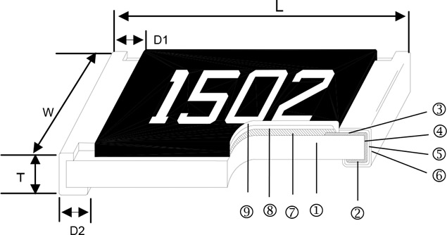 Anti-Corrosive Thin Film Resistor Resistor Construction (PR) |
① | Alumina Substrate | |||
| ② | Bottom Electrode | ||||
| ③ | Top Electrode | ||||
| ④ | Edge Electrode | ||||
| ⑤ | Barrier Layer | ||||
| ⑥ | External Electrode | ||||
| ⑦ | Resistor Layer | ||||
| ⑧ | Primary Overcoat | ||||
| ⑨ | Secondary Overcoat | ||||
| |
|||||
| Type | L (Unit: mm) | W (Unit: mm) | T (Unit: mm) | D1 (Unit: mm) | D2 (Unit: mm) | Weight(g)/1000pcs |
| PR02 (0402) | 1.00±0.05 | 0.50±0.05 | 0.35±0.05 | 0.20±0.10 | 0.20±0.10 | 0.55 |
| PR03 (0603) | 1.55±0.10 | 0.80±0.10 | 0.45±0.10 | 0.30±0.20 | 0.30±0.20 | 1.85 |
| PR05 (0805) | 2.00±0.15 | 1.25±0.15 | 0.55±0.10 | 0.35±0.20 | 0.40±0.25 | 4.76 |
| PR06 (1206) | 3.05±0.15 | 1.55±0.15 | 0.55±0.10 | 0.42±0.20 | 0.35±0.25 | 9.11 |
| PR10 (2010) | 4.90±0.15 | 2.40±0.15 | 0.55±0.10 | 0.60±0.30 | 0.50±0.25 | 23.82 |
| PR12 (2512) | 6.30±0.15 | 3.10±0.15 | 0.55±0.10 | 0.60±0.30 | 0.50±0.25 | 38.46 |
Standard Electrical Specifications (PR)
| Type | Power Rating at 70°C |
Operating Temp. Range | Max Operating Voltage | Max Overloading Voltage | Resistance Tolerance % | Resistance Range | TCR PPM/°C |
| PR02 (0402) |
1/16W | -55 ~ +155°C | 25V | 50V | ±0.1, ±0.25, ±0.5 | 49.9Ω~12KΩ | ±15 |
| 24.9Ω~24.9KΩ | ±25, ±50 | PR03 (0603) |
1/16W | -55 ~ +155°C | 50V | 100V | ±0.1, ±0.25, ±0.5 | 24.9Ω~332KΩ | ±15, ±25, ±50 |
| PR05 (0805) |
1/10W | -55 ~ +155°C | 100V | 200V | ±0.1, ±0.25, ±0.5 | 10Ω~1MΩ | ±15, ±25, ±50 |
| PR06 (1206) |
1/8W | -55 ~ +155°C | 150V | 300V | ±0.1, ±0.25, ±0.5 | 10Ω~1MΩ | ±15, ±25, ±50 |
| PR10 (2010) |
1/4W | -55 ~ +155°C | 150V | 300V | ±0.1, ±0.25, ±0.5 | 24.9Ω~1MΩ | ±15 |
| 10Ω~1.5MΩ | ±25, ±50 | ||||||
| PR12 (2512) |
1/2W | -55 ~ +155°C | 150V | 300V | ±0.1, ±0.25, ±0.5 | 24.9Ω~1MΩ | ±15 |
| 10Ω~1.5MΩ | ±25, ±50 |
|
High Power Rating Electrical Specifications (PR)
| Type | Power Rating at 70°C |
Operating Temp. Range | Max Operating Voltage | Max Overloading Voltage | Resistance Tolerance % | Resistance Range | TCR PPM/°C |
| PR03 (0603) |
1/10W | -55 ~ +155°C | 75V | 150V | ±0.1, ±0.25, ±0.5 | 24.9Ω~220KΩ | ±15, ±25, ±50 |
| PR05 (0805) |
1/8W | -55 ~ +155°C | 150V | 300V | ±0.1, ±0.25, ±0.5 | 24.9Ω~680KΩ | ±15, ±25, ±50 |
| PR06 (1206) |
1/4W | -55 ~ +155°C | 200V | 400V | ±0.1, ±0.25, ±0.5 | 24.9Ω~1MΩ | ±15, ±25, ±50 |
|
Recommend Land Pattern (Unit: mm) (PR)
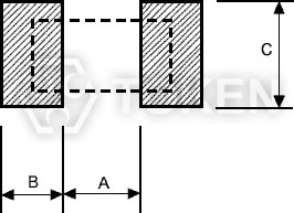 Recommend Land Pattern (PR) |
Codes | A | B | C |
| PR02 (0402) | 0.50 | 0.50 | 0.60±0.2 | |
| PR03 (0603) | 0.80 | 1.00 | 0.90±0.2 | |
| PR05 (0805) | 1.00 | 1.00 | 1.35±0.2 | |
| PR06 (1206) | 2.00 | 1.15 | 1.70±0.2 | |
| PR10 (2010) | 3.60 | 1.40 | 2.50±0.2 | |
| PR12 (2512) | 4.90 | 1.60 | 3.10±0.2 |
Power Derating Curve (PR)
|
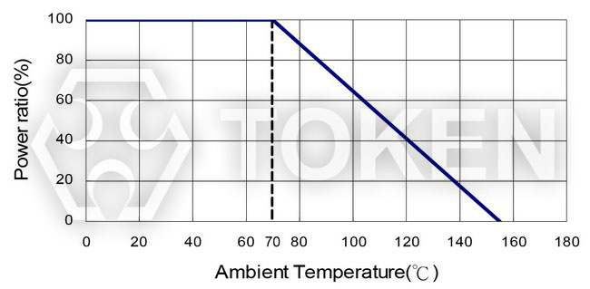 Power Derating Curve (PR) Series
Soldering Condition (PR)
|
|
|
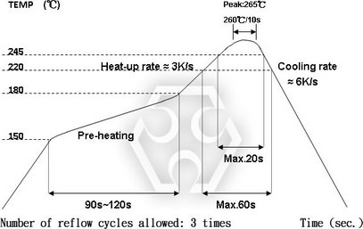 IR Reflow Soldering
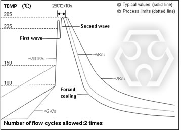 Wave Soldering (Flow Soldering)
Environmental Characteristics (PR)
| Test Item | Specification | Test Method | |
| Size 0603/0805/1206/2010/2512 | Size 0402 | ||
| Short Time Overload | ≤ ±0.02% | ≤ ±0.1% | JIS-C-5201-1 5.5 RCWV*2.5 or Max Overloading Voltage, 2 seconds |
| ≤ ±0.2% for high power rating | |||
| Thermal Shock | ≤ ±0.02% | ≤ ±0.1% | MIL-STD-202F Method 107G -55°C~125°C, 100 cycles |
| Load Life (Endurance) |
≤ ±0.05% | ≤ ±0.25% | MIL-STD-202F Method 108A RCWV, 70°C, 1.5 hours ON, 0.5 hours OFF, total 1000 hours |
| ≤ ±0.25% for high power rating | |||
| Humidity (Steady State) (Damp Heat with Load) |
≤ ±0.05% | ≤ ±0.5% | MIL-STD-202F Method 103B 40±2°C, 90~95%RH, RCWV 1.5 hours ON, 0.5 hours OFF, total 1000 hours |
| ≤ ±0.25% for high power rating | |||
| Resistance to Dry Heat |
≤ ±0.05% | ≤ ±0.5% | JIS-C-5202-7.2 1000 hours @ +155°C without load |
| Resistance to Soldering Heat |
≤ ±0.02% | ≤ ±0.1% | MIL-STD-202F Method 210E 260±5°C, 10±1seconds |
| Solderability | 95%min coverage | MIL-STD-202F Method 208H 245°C±5°C, 3±0.5(sec) |
|
|
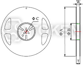
Packaging Quantity & Reel Specifications (Unit: mm) (PR)
|
||||||||
| Codes | ΦA (Unit: mm) | ΦB (Unit: mm) | ΦC (Unit: mm) | W (Unit: mm) | T (Unit: mm) | Paper Tape (PCS) |
Emboss Plastic Tape (PCS) |
|
| PR02 (0402) | 178.0±1.0 | 60.0±1.0 | 13.5±0.7 | 9.5±1.0 | 11.5±1.0 | 10,000 | - | |
| PR03 (0603) | 178.0±1.0 | 60.0±1.0 | 13.5±0.7 | 9.5±1.0 | 11.5±1.0 | 5,000 | - | |
| PR05 (0805) | 178.0±1.0 | 60.0±1.0 | 13.5±0.7 | 9.5±1.0 | 11.5±1.0 | 5,000 | - | |
| PR06 (1206) | 178.0±1.0 | 60.0±1.0 | 13.5±0.7 | 9.5±1.0 | 11.5±1.0 | 5,000 | - | |
| PR10 (2010) | 178.0±1.0 | 60.0±1.0 | 13.5±0.7 | 13.5±1.0 | 15.5±1.0 | - | 4,000 | |
| PR12 (2512) | 178.0±1.0 | 60.0±1.0 | 13.5±0.7 | 13.5±1.0 | 15.5±1.0 | - | 4,000 | |
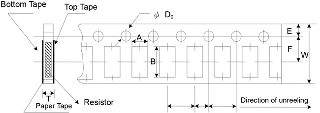
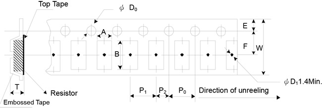
Paper Tape Specifications (Unit: mm) (PR)
|
|||||||||||
| Codes | A (mm) | B (mm) | W (mm) | E (mm) | F (mm) | P0 (mm) | P1 (mm) | P2 (mm) | ΦD0 (mm) | T (mm) | |
| PR02 | 0.70±0.05 | 1.16±0.05 | 8.00±0.10 | 1.75±0.05 | 3.5±0.05 | 4.00±0.10 | 2.00±0.05 | 2.00±0.05 | 1.55±0.05 | 0.40±0.03 | |
| PR03 | 1.10±0.05 | 1.90±0.05 | 8.00±0.10 | 1.75±0.05 | 3.5±0.05 | 4.00±0.10 | 4.00±0.10 | 2.00±0.05 | 1.55±0.05 | 0.60±0.03 | |
| PR05 | 1.60±0.05 | 2.37±0.05 | 8.00±0.10 | 1.75±0.05 | 3.5±0.05 | 4.00±0.10 | 4.00±0.10 | 2.00±0.05 | 1.55±0.05 | 0.75±0.05 | |
| PR06 | 2.00±0.05 | 3.55±0.05 | 8.00±0.10 | 1.75±0.05 | 3.5±0.05 | 4.00±0.10 | 4.00±0.10 | 2.00±0.05 | 1.55±0.05 | 0.75±0.05 | |
Paper Tape Peel Force (PR)
|
|
|
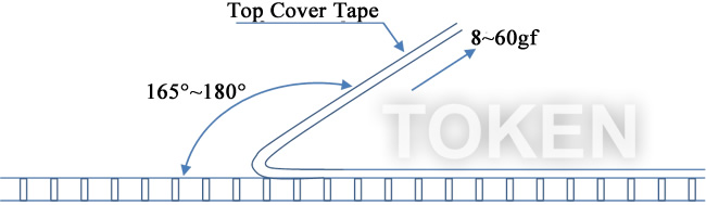 Paper Tape Peel Force
Emboss Plastic Tape Specifications (Unit: mm) (PR)
|
|||||||||||
| Codes | A (mm) | B (mm) | W (mm) | E (mm) | F (mm) | P0 (mm) | P1 (mm) | P2 (mm) | ΦD0 (mm) | T (mm) | |
| PR10 | 2.85±0.10 | 5.45±0.10 | 12.0±0.10 | 1.75±0.10 | 5.5±0.05 | 4.00±0.05 | 4.00±0.10 | 2.00±0.05 | 1.50±0.10 | 1.00±0.20 | |
| PR12 | 3.40±0.10 | 6.65±0.10 | 12.0±0.10 | 1.75±0.10 | 5.5±0.05 | 4.00±0.05 | 4.00±0.10 | 2.00±0.05 | 1.50±0.10 | 1.00±0.20 | |
Emboss Tape Peel Force (PR)
|
|
|
 Emboss Tape Peel Force
Order Codes (PR)
| PR | 02 | D | TR | C3 | U | 1002 | ||||||||||||||||||||||||||||||||||||||||||||||||||||||||||||||||||||||
| 1 | 2 | 3 | 4 | 5 | 6 | 7 | 8 | |||||||||||||||||||||||||||||||||||||||||||||||||||||||||||||||||||||
|
|
|
|
|
|
|
|
|||||||||||||||||||||||||||||||||||||||||||||||||||||||||||||||||||||
0805~2512 4 digits marking for Example Marking
| Resistance | 100Ω | 2.2KΩ | 10KΩ | 49.9KΩ | 100KΩ | 1MΩ |
| Marking | 1000 | 2201 | 1002 | 4992 | 1003 | 1004 |
0603: 3 digits Marking E24 Nominal Table
| E24 code | 10 | 11 | 12 | 13 | 15 | 16 | 18 | 20 | 22 | 24 | 27 | 30 | 33 | 36 | 39 | 43 | 47 | 51 | 56 | 62 | 68 | 75 | 82 | 91 |
|
Marking Table E96 Nominal Table
| code | 02 | 03 | 04 | 06 | 07 | 08 | 09 | 10 | 11 | 13 | 14 | 15 | 16 | 17 | 19 | 20 | 21 | 22 | 23 | 24 | 25 | 26 | 27 |
| E96 | 102 | 103 | 107 | 113 | 115 | 118 | 121 | 124 | 127 | 133 | 137 | 140 | 143 | 147 | 154 | 158 | 162 | 165 | 169 | 174 | 178 | 182 | 187 |
| code | 28 | 29 | 31 | 32 | 33 | 34 | 35 | 36 | 37 | 38 | 39 | 40 | 41 | 42 | 43 | 44 | 45 | 46 | 47 | 48 | 49 | 50 | 51 |
| E96 | 191 | 196 | 205 | 210 | 215 | 221 | 226 | 232 | 237 | 243 | 249 | 255 | 261 | 267 | 274 | 280 | 287 | 294 | 301 | 309 | 316 | 324 | 332 |
| code | 52 | 53 | 54 | 55 | 56 | 57 | 58 | 59 | 60 | 61 | 62 | 63 | 64 | 65 | 66 | 67 | 68 | 69 | 70 | 71 | 72 | 73 | 74 |
| E96 | 340 | 348 | 357 | 365 | 374 | 383 | 392 | 402 | 412 | 422 | 432 | 442 | 453 | 464 | 475 | 487 | 499 | 511 | 523 | 536 | 549 | 562 | 576 |
| code | 75 | 76 | 77 | 78 | 79 | 80 | 81 | 82 | 83 | 84 | 86 | 87 | 88 | 89 | 90 | 91 | 92 | 93 | 94 | 95 | 96 | ||
| E96 | 590 | 604 | 619 | 634 | 649 | 665 | 681 | 698 | 715 | 732 | 768 | 787 | 806 | 825 | 845 | 866 | 887 | 909 | 931 | 953 | 976 |
Multiplier E96 Marking
| Code | A | B | C | D | E | F | X | Y |
| Multiplier | 100 | 101 | 102 | 103 | 104 | 105 | 10-1 | 10-2 |
More Information of Resistors in PDF Download
Low Resistance Resistors, Sufrace Mount Chip Resistor Series PDF download (1,356KB).
Sufrace Mount Terminology & Glossary PDF download (398KB).
Chip Resistor Application Notes PDF download (222KB).
General Information of Chip Resistor download (208KB).
Selecting The Optimum Resistors PDF download (234KB).
Common Resistor Terminology PDF download (315KB).
Resistor Precautions in Usage PDF download (301KB).
Typical RoHS Reflow Profile PDF download (303KB).
What is a Resistor PDF download (562KB).