Dielectric Filters
(DF-B)- Within "DF Series" Section :
- 1. (DF-A) Two Block Dielectric Filter
- 2. (DF-B) Two Block Dielectric Filter
- 3. (DF-C/D) Two Block Dielectric Filter
- 4. (DF) - 3 or More Poles Filters
- 5. (BP-R) Band-Pass Filters
- 6. (LJ) Lead-Type RF Filters
- 7. (BP-S) High Performance Microwave Filters
Introduction (DF-B)
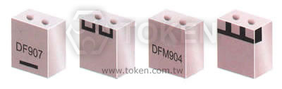
Best Performance With A Ripple Bandwidth 0.5(dB) max. (DF-B)
Token Dielectric Filter (DF-B) has a Ripple in Band Width (dB) 0.5 max. Token (DF-B) filter manufactures with a fine-grained, high density, high purity dielectric material to keep the best performance with a ripple in band width (dB) 0.5 max.
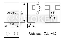
The (DF-B) filter's small size (8.5 x 6.0 x 3.0 mm) means they require more less mounting space. Available Center Frequency 650 MHz to 916 MHz with V.S.W.R 1.5 max., insertion loss 2.0 ~ 5.0 (dB) max.
RF dielectric filters are mounted in a surface mount package which assures mechanical stability and excellent lead coplanarity. RF filters can be customed designs and tighter tolerances available on request.
Products conform to the RoHS directive. Application of specific designs also available including different Dielectric values and Q specifications adjusted to frequency requirements.
Filters (DF-B) Dimensions (Unit: mm)
|
Typical Specifications (DF-B)
| Part No. | Center Frequency (MHz) |
Band Width (MHz) |
Insertion Loss (dB) max. |
Ripple in Band Width (dB) max. |
V.S.W.R max. |
Attenuation (dB) min. (MHz) |
| DF650S30B | 650 | fo±15 | 2.5 | 0.5 | 1.5 | 19 at fo±64 |
| DF700S20B | 700 | fo±10 | 2.5 | 0.5 | 1.5 | 19 at fo±64 |
| DF710S08B | 710 | fo±4 | 5.0 | 0.5 | 1.5 | 35 at fo+100; 28 at fo+50 |
| DF746S20B | 746 | fo±10 | 2.5 | 0.5 | 1.5 | 12 at fo-20 |
| DF758S16B | 758 | fo±8 | 2.5 | 0.5 | 1.5 | 19 at fo±64 |
| DF794S20B | 794 | fo±10 | 2.5 | 0.5 | 1.5 | 19 at fo±64 |
| DF800S08B | 800 | fo±4 | 5.0 | 0.5 | 1.5 | 35 at fo+100; 28 at fo+50 |
| DF836S20B | 836 | fo±10 | 2.5 | 0.5 | 1.5 | 19 at fo+52 |
| DF850S08B | 850 | fo±4 | 5.0 | 0.5 | 1.5 | 30 at fo+100; 40 at fo-200 |
| DF863S22B | 863 | fo±11 | 2.0 | 0.5 | 1.5 | 50 at fo-90; 20 at fo+90 |
| DF875S24B | 875 | fo±12 | 2.3 | 0.5 | 1.5 | 30 at fo-70 |
| DF903S09B | 903 | fo±4.5 | 3.5 | 0.5 | 1.5 | 34 at fo-64; 41 at fo+64 |
| DF906S20B | 906 | fo±10 | 2.5 | 0.5 | 1.5 | 19 at fo±64 |
| DF916S30B | 916 | fo±15 | 2.7 | 0.5 | 1.5 | 20.5 at fo±70 |
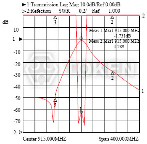
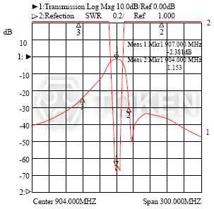
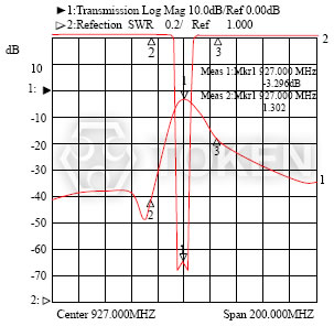
Typical Characteristic (DF-B)
| |
|
|
|
Order Codes (DF-B)
| DF | 836 | S | 20 | B | |||||||||||||||||
| 1 | 2 | 3 | 4 | 5 | |||||||||||||||||
|
|
|
|
|
|||||||||||||||||
More Information of Microwave Dielectric Filters in PDF download
Mechanical Stability And Excellent Lead Coplanarity (DF-B) Series PDF download (504KB).
Information Of Microwave Dielectric Components PDF download (218KB).
Dielectric Filter Technology & Saw Filter Technology PDF download (191KB).
Terminology & Glossary Of Dielectric Resonator Antenna and Filters PDF download (338KB).
Design Notice & Technology Of Resonators & Filters PDF download (423KB).
Redial Taping Dimensions Of Ceramic Resonator & Filter PDF download (407KB).
Piezo Dielectric Microwave Devices Precaution Usage PDF download (393KB).
About What Is a Piezo - Ceramic Information PDF download (479KB).