Dielectric Filters
(DF-C/D)- Within "DF Series" Section :
- 1. (DF-A) Two Block Dielectric Filter
- 2. (DF-B) Two Block Dielectric Filter
- 3. (DF-C/D) Two Block Dielectric Filter
- 4. (DF) - 3 or More Poles Filters
- 5. (BP-R) Band-Pass Filters
- 6. (LJ) Lead-Type RF Filters
- 7. (BP-S) High Performance Microwave Filters
Introduction (DF-C/D)
Customed Designs and Standard Parts Are Available (DF-C/D)
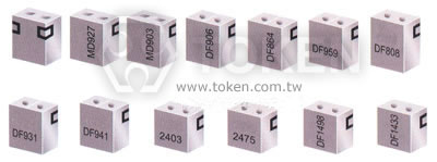
Token Two Block-Type Dielectric Filters (DF-C/D) range up to 5.8GHz.
Token two block-type dielectric RF filters have been designed for cellular basestation applications that use a digital pre-distortion amplifier (DPD), as they feature a wide pass band and flat ripple performance, which are required for DPD PA design.
Applications also include RF and microwave communications such as satellite and TV transmission, wireless security systems, radar, GSM, 3G, GPS, CT1, CT2, 900MHz, 1.8GHz, 2.4GHz, 5.8GHz Cordless Phone, wireless earphone, wireless microphone, aerospace and military.
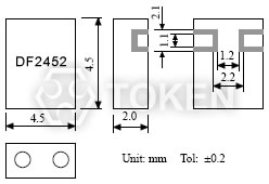
The (DF-C/D) filter's small size (4.5 x 4.5 x 2.0 mm) means they require more less mounting space with a ripple of 1.0 dB max and insertion loss 2.0 (dB) max. Center frequency range from 1575 MHz to 5800 MHz with V.S.W.R 2.0 max.
The surface mount RF Dielectric Filters (DF-C/D) conform to the RoHS directive and package is suitable for automatic pick and place equipment which assures mechanical stability and excellent lead coplanarity. Customed designs and tighter tolerances are available on request. Application of specific designs also available including different Dielectric values and Q specifications adjusted to frequency requirements.
Dimensions (Unit: mm) (DF-C/D)
|
Typical Specifications (DF-C/D)
| Part No. | Center Frequency (MHz) |
Band Width (MHz) |
Insertion Loss (dB) max. |
Ripple in Band Width (dB) max. |
V.S.W.R max. |
Attenuation (dB) min. (MHz) |
| DF1575S40C | 1575 | fo±20 | 2.0 | 0.7 | 2.0 | 20 at fo-100; 18 at fo+100 |
| DF1855S70C | 1855 | fo±35 | 2.0 | 0.7 | 2.0 | 20 at fo+300; 20 at fo-300 |
| DF1890S80C | 1890 | fo±40 | 2.0 | 0.7 | 2.0 | 15 at fo+250; 35 at fo-250 |
| DF1950S90C | 1950 | fo±45 | 3.0 | 0.7 | 2.0 | 45 at fo+975; 45 at fo-975 |
| DF2332S100C | 2332 | fo±50 | 2.5 | 0.7 | 2.0 | 25 at fo+500; 40 at fo-500 |
| DF2450S100C | 2450 | fo±50 | 2.0 | 0.7 | 2.0 | 12 at fo+250; 15 at fo-250 |
| DF3066S170D | 3066 | fo±85 | 2.0 | 1.0 | 2.0 | 10 at fo+300; 15 at fo-300 |
| DF3480S120D | 3480 | fo±60 | 2.0 | 1.0 | 2.0 | 10 at fo+500; 20 at fo-500 |
| DF3650S150D | 3650 | fo±75 | 2.0 | 1.0 | 2.0 | 15 at fo+750; 25 at fo-750 |
| DF4880S160D | 4880 | fo±80 | 2.0 | 1.0 | 2.0 | 5 at fo+350; 15 at fo-350 |
| DF5800S200D | 5800 | fo±100 | 2.0 | 1.0 | 2.0 | 5 at fo+400; 15 at fo-400 |
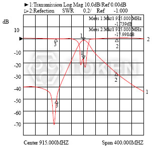
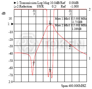
Typical Characteristic (DF-C/D)
| |
|
Order Codes (DF-C/D) For 2 Pole
| DF | 1950 | S | 90 | C | |||||||||||||||||
| 1 | 2 | 3 | 4 | 5 | |||||||||||||||||
|
|
|
|
|
|||||||||||||||||
Two Block-Type Dielectric Filters (DF-C/D) PDF download
Wide Pass Band And Flat Ripple Performance RF Dielectric Filters (DF - C / D) Series PDF download (504KB).
Typical RoHS Reflow Profile PDF download (287KB).
Resonators & Filters Terminology PDF download (491KB).
About What Is a Piezo - Ceramic Information PDF download (479KB).
Piezo Dielectric Microwave Devices Precaution Usage PDF download (393KB).
Information Of Microwave Dielectric Components PDF download (218KB).
Design Notice & Technology Of Resonators & Filters PDF download (423KB).
Dielectric Filter Technology & Saw Filter Technology PDF download (191KB).
Redial Taping Dimensions Of Ceramic Resonator & Filter PDF download (407KB).
Terminology & Glossary Of Dielectric Resonator Antenna and Filters PDF download (338KB).