Ceramic Filters
(LT10.7M)Introduction (LT10.7M)
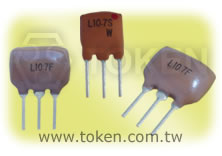
Token (LT10.7M) ceramic filters are compatible with Murata SFELF10M7. Token LT10.7M series are monolithic devices which utilize the energy-trapped thickness vibration-mode. This principle of operation is based upon the fact that an excellent resonating element with low spurious vibration can be obtained by adhering to certain theoretical parameters of design. These parameters include the physical dimensions of the peizo element, the electrode pattern, and the associated mass loading effect of the electrodes.
Token categorizes the LT 10.7 family according to rank of center frequency. This ranking indicates that a given LT 10.7 will be marked with one of the colors listed in the following chart and will exhibit the center frequency in Technical Characteristics Table.
The (LT10.7M) offers three series: LT10.7M for FM Receiver (Compatible Murata SFELF10M7), LT10.7M A10 Insertion Loss 2.5±2.0 db ~ 4.5±2.0 db (Compatible Murata SFELF10M7 A10), and LT10.7M Wide Band-width 950 kHz at 20dB/Narrow Band-width 95 kHz at 20dB (Compatible Murata Filter SFELF10M7 DBS Receiver).
(LT10.7M) Narrow Band-width series features stable low spurious and temperature characteristics. This series is suitable for European car-audio or AM up conversion use that needs narrow band characteristics are stable. LT10.7M Wide Band-width series are specified to make up conventional ceramic filters which wider band characteristics not obtained.
Custom parts are available on request. Token will also produce devices outside these specifications to meet specific customer requirements,
please contact our sales for more information.
Benefit Features :
- Change in center frequency is typically within ±30ppm/°C at -20°C to +80°C.
- Various band widths are available for applications in wide to narrow bands.
- Low loss, favorable waveform symmetry, and high selectivity.
- These miniature filters have high mechanical strength.
- Excellent shape factor of frequency response.
- Small dispersion and stable characteristics.
- Good waveform symmetry.
- High reliability.
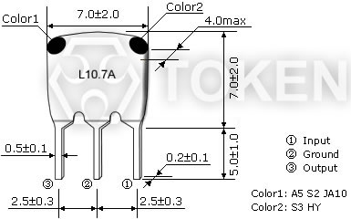
Dimensions (Unit: mm) (LT10.7M)
|
Technical Characteristics (LT10.7M) For FM Receiver (Murata SFE10M7 FM-IF Compatible)
| Part Number | 3dB Band Width (kHz) | 20dB Band Width (kHz) max | Insertion Loss (dB) max | Spurious Attenuation (9-12MHz)(dB)min |
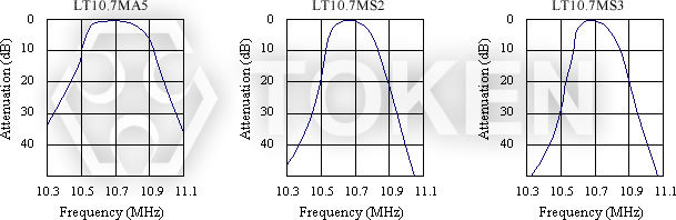
| LT10.7MA5 | 280±50 | 650 | 6 | 30 |
| LT10.7MS2 | 230±50 | 600 | 6 | 40 |
| LT10.7MS3 | 180±40 | 520 | 7 | 40 |
Input/Ouput Impedance: 330Ω
Technical Characteristics (LT10.7M A10) Low Insertion Loss (Murata SFE10M7 A10 Compatible)
| Part Number | 3dB Band Width (kHz) | 20dB Band Width (kHz) max | Insertion Loss (dB) | Spurious Attenuation (9-12MHz)(dB)min |
| LT10.7MA5A10 | 280±50 | 590 | 2.5±2.0 | 30 |
| LT10.7MS2A10 | 230±50 | 520 | 3.0±2.0 | 35 |
| LT10.7MS3A10 | 180±40 | 470 | 3.5±1.5 | 35 |
| LT10.7MJA10 | 150±40 | 360 | 4.5±2.0 | 35 |
Input/Ouput Impedance: 330Ω
Technical Characteristics (LT10.7M) Wide/Narrow Band-width (Murata SFE10M7 DBS Receiver Compatible)
| Part Number | 3dB Band Width (kHz) | 20dB Band Width (kHz) max | Insertion Loss (dB) | Spurious Attenuation (9-12MHz)(dB)min |
| LT10.7MA19 | 350min | 950 | 3.0±2.0 | 20 |
| LT10.7MA20 | 330±50 | 680 | 4.0±2.0 | 30 |
| LT10.7MHY | 110±30 | 350 | 7.0±2.0 | 30 |
| LT10.7MFP | 20min | 95 | 6.0max | 24(10.7±1.0MHz) |
Input/Ouput Impedance: 470Ω(MA19), 330Ω(MA20,MHY), 600Ω(MFP)
Characteristics (LT10.7M)
|
Matching Conditions & Test Circuit (LT10.7M)
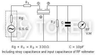
(LT10.7M) Test Circuit
- When using filters, it is most important to match the input/output load to impedance 330 ohm (LT10.7MA19 is 470 ohm matching). Waveform symmetry is damaged when reactance is added to the input/output load.
- Two filters directly connected can be used for high selectivity. For reducing waveform variation, it is recommended to input a buffer AMP between filters.
- The LT10.7M series are of input/output symmetric structure so that in theory there is no input/output directionality. Actual circuits may use different input/output loading conditions (for example, mismatched impedance) or capacitance load. In such cases, the waveform will be a little changed by the direction of the input/output of the filter.
Standard Marking Color (LT10.7M)
| Center Frequency | Color |
| D:10.64MHz±30kHz | Black |
| B:10.67MHz±30kHz | Blue |
| A:10.70MHz±30kHz | Red |
| C:10.73MHz±30kHz | Orange |
| E:10.76MHz±30kHz | White |
Order Codes (LT10.7M)
| LT10.7MA5 | - | A | P | ||||||||||||||||||||||||||||||
| 1 | 2 | 3 | |||||||||||||||||||||||||||||||
|
|
|
|||||||||||||||||||||||||||||||
More Information About Ceramic Filters in PDF download
Good Waveform Symmetry, Small Dispersion, And High Selectivity Filters (LT10.7) Series PDF download (342KB).
Typical RoHS Reflow Profile PDF download (287KB).
Resonators & Filters Terminology PDF download (491KB).
General Information Of Ceramic Filters PDF download (199KB).
About What Is a Piezo - Ceramic Information PDF download (479KB).
Crystal Ceramic Resonators All Series material PDF download (905KB).
Terminologies Of Filter Characteristic Properties PDF download (346KB).
Design Notice & Technology Of Resonators & Filters PDF download (423KB).
Piezo Dielectric Microwave Devices Precaution Usage PDF download (393KB).
Redial Taping Dimensions Of Ceramic Resonator & Filter PDF download (407KB).